Simple Projects Using LED | Dimmer Circuit, Emergency LED, and Dancing Lights
If you think of making simple projects using LED, then you’re at the right place. Because we are going to show you some fantastic projects using LED in this article. We have demonstrated 3 different LED projects with simple circuits, and you can easily make these projects using some cheap and common components such as microcontrollers, especially with Microchip PIC microcontrollers, 555 timers, etc.
Here are the projects using LED that are described below:
- PWM LED Dimmer Circuit: You can control the brightness of the LED using this circuit.
- 12v Emergency LED Light Circuit Diagram: The LED bulbs will consume very little energy and can be used as a night light during main power loss.
- Dancing Lights: You can use this beautiful project at any entertainment party.
So, let’s read by the end of this article thoroughly and select your desired LED project.
1. PWM LED Dimmer Circuit | Brightness Control by 555 Timer
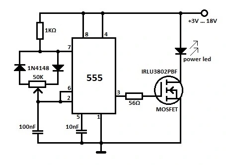
LED is basically a diode. When the forward voltage (Forward bias) exceeds 0.7 volts, it starts to glow and if the forward voltage is less than 0.7 volts, it turns off. Now, what happens if you forward a higher voltage to the LED? Will it increase the brightness? No, if you do so, you’ll end up burning those LEDs.So what can you do to adjust the brightness of LEDs? Well, you just need a simple LED brightness control circuit using (The pulse Width Modulation) PWM method which is called the PWM LED dimmer circuit. We have already discussed the mechanism of controlling the brightness of LED in the PWM signal generation. To produce this PWM circuit, we have used an NE 555 timer IC.
LED Dimmer Circuit Schematic
Components Required for LED Dimmer Controller
- Resistors (4.7kΩ)
- Potentiometer (10kΩ)
- Capacitor (100nF or 0.1µF)
- 555 timer IC
Working of PWM LED Light Dimmer Circuit
- Pulse Width Modulation (PWM) is itself a discourse. Op-Amps and 555 ICs are widely used for generating PWM signals.
- This circuit is based on 555 timer IC. You can use this circuit as a dimmer switch for LED lights. This PWM concept is also applicable to lamp dimmer switches too. But here we are applying that directly to the LED.
- At the instant of turning the circuit on, the output will be 5V. It’s because the voltage at the 2nd pin (trigger pin) is less than 1/3 Vcc. [Read Astale Multivibrator for getting familiarized with 555 timer].
- At the very next moment, the output voltage will reach the capacitor via the 10kΩ potentiometer and diode D2. So, the capacitor starts charging with a time constant RdR1C (where Rd is the forward resistance of Diode D2).
- When the capacitor voltage exceeds 2/3 Vcc, the 555 timer gets reset. Then the output will be 0V.
- At this moment the capacitor discharges via the diode D1 and potentiometer R1 to the output pin since it is in ground potential.
- When the capacitor voltage goes below 1/3 Vcc, the output of 555 IC again rises to 5V. This process continues.
- Here the charging and discharging path is entirely different since it is isolated by diodes D1 and D2 (refer above images). If the potentiometer midpoint is at 50% (middle), we will able to get 50% duty cycle (square waves of equal pulse width).
- Pulse width can be varied by changing the charging and discharging time, this is possible by adjusting the potentiometer. Thus we get a PWM signal…!
- This signal is applied to the LED via a 4.7kΩ resistor. The brightness of the LED is proportional to the average value of the square wave.
- For high pulse width, it is possible to get huge brightness of LED. Also, if it is a low pulse width, the brightness also decreases.
- Please watch the design simulation video and practical implementation of the circuit given below for a better understanding.
A Video Description of PWM LED Light Dimmer
This is the video practical implementation of the PWM LED dimmer circuit.
(We express our gratitude to Mr. Giorgos Lazaridis for providing this video http://www.pcbheaven.com/circuitpages/LED_PWM_Dimmer)
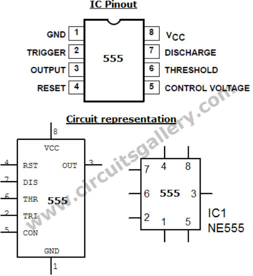
Pinout of 555 timer IC
Reducing source voltage is the easiest but never a smart way to control the brightness of an LED. PWM lets you vary the duty cycle and achieve the required adjustment without altering the voltage or invoking any power loss. In this case, you just need to protect the MOSFET with a heat sink.
2. 12v Emergency LED Light Circuit Diagram With Practical Prototype
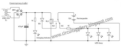
LED bulbs consume very little amount of energy. We will show you how you can make an emergency LED light circuit that will glow automatically when main power failures take place. The main thing you’re going to need is a relay. It will automatically reserve the DC voltage to the battery from the main AC power and whenever the main power supply will stop, it will connect LEDs to the battery.
Circuit Diagram of Emergency LED Light Circuit
Components Required for Emergency 12V LED Light Circuit
- Step down transformer-1 (230V to 12V)
- Diodes-5 (1N4007)
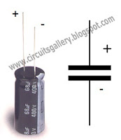
- Capacitor-1 (470µF)
- Led-1 (Red)
- Resistors-2 (1K)
- Relay-1 (12V)
- Rechargeable Battery-1 (12V)
- Switch
- LED Array (Group of LEDs, See my prototype )
Working Principle of Emergency Light Circuit With 12V LEDs
- The step down transformer and the diode bridge rectifier steps down and convert the high AC (in the range of 110V or 230V) voltage to low (12V) DC voltage.
- The diode D2 prevents the battery charge from flowing back, it acts as a freewheeling diode too.
- In the presence of electricity, the relay contact connects the NO (Normally Open) terminal to the battery. Thus, battery charges during this time.
- We are using a red LED as the charging indicator which glows when the emergency light battery is charging.
- When supply failure occurs, the relay connects the NC (Normally Closed) terminal to the battery.
- The LED arrays are connected to the NC terminal, thus they glow by using the charge stored in the battery.
Datasheets and Components Pinout
Here are the datasheets of diodes: 1N4001-1N4007.
My Emergency LED Light Prototype
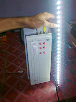
You may use any bulb in this circuit. All you need to know is the principle and the operation of the relay. But as other bulbs like tungsten consume more energy than LEDs, this project is the best for emergency lights using DC power.
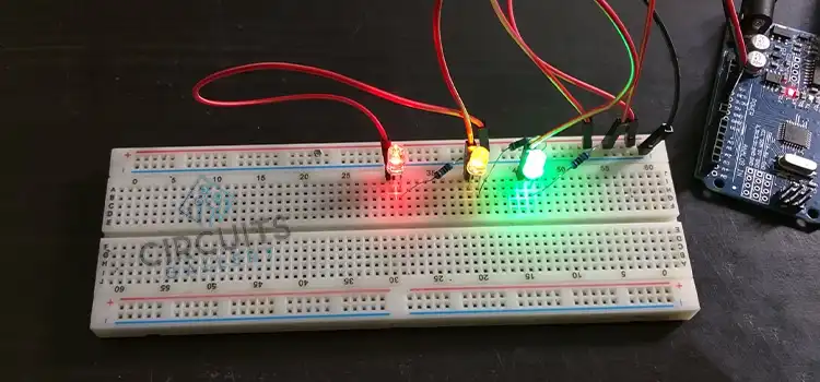
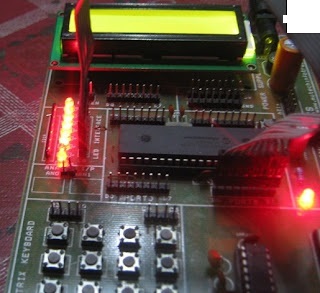
3. LED Dancing light using PIC Microcontroller | Beginner’s guide
Dancing or running lights can be easily implemented using microcontrollers. To make this running light, you will need a 40-pin IC PIC microcontroller such as PIC16F877A and LED bulbs. The LEDs will be connected to port B, and they will twinkle according to the microcontroller C program providing a dancing effect for the viewer.The Micro C compiler is used for this PIC programming which is a popular C language compiler for the PIC16F8xxx family, and it has a wide variety of inbuilt functions (library functions). You can download it from the Micro C website.
LED Blinking Microcontroller C Program
void main()
{
    TRISB=0x00;
    while(1)
    {
        PORTB=0x81;
        delay_ms(100);
        PORTB=0x42;
        delay_ms(100);
        PORTB=0x24;
        delay_ms(100);
        PORTB=0x18;
        delay_ms(100);
        PORTB=0x24;
        delay_ms(100);
        PORTB=0x42;
        delay_ms(100);
    }
}
This is a tested and verified embedded program.
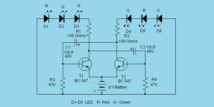
Dancing Light Circuit Diagram
Conclusion
LED projects are so simple and parallelly attractive too. You can make your project more charming using some simple and common ICs like PIC microcontrollers. We have demonstrated 3 different types of projects using LEDs and hopefully, you have now found your desired LED project from this article. If you face any issues while developing these projects, then don’t hesitate to ask in our comment section below. Best wishes for your upcoming project.
Subscribe to our newsletter
& plug into
the world of circuits
![[Explained] What Is the Difference Between Fader and Gain?](https://www.circuitsgallery.com/wp-content/uploads/2023/08/What-Is-the-Difference-Between-Fader-and-Gain.webp)
![[5 Fixes] Getting Voltage but No Amps](https://www.circuitsgallery.com/wp-content/uploads/2023/06/Getting-Voltage-but-No-Amps.webp)

