DC Motor Control Circuits | Motor Driver Projects
DC Motor (control) driver circuits are the essential circuit of the Robotics workshops. If you are a robotic beginner and looking for motor driver projects, then this article is just for you.
We will discuss the basics of some motor driver and robotics projects and will demonstrate 7 different unique projects based on DC motor control circuits which you can make at your home or college at a very low cost. Here is the list –
- H Bridge Motor Driver Circuit: it is certainly a great topic in Robotics engineering and automation and the H Bridge motor (driver) controllers are the most common circuits for innumerable robotics hobbyists.
- Remote Controlled DC Motor: This is very useful in autonomous robots, line follower robots, etc.
- Bidirectional Motor Control (Driver) Circuit: Where you’re going to learn how to rotate a DC motor in clockwise and anti-clockwise directions.
- Servo Motor Control: This is widely used in robotics and industries for motion control.
- How to Control & Program Stepper Motor: As we all know that stepper motor driver plays an important role in the automatic control system, you also learn to program this circuit here.
- DC Motor Interfacing With Pic Microcontroller: This is a very basic and simple project for Robotics engineering and automation beginners.
- Remote Controlled DC Motor for Toy Car Circuit Diagram: This is a simple circuit for a toy car which is the best for electronics beginners.
So, don’t miss these amazing projects, and let’s read by the end of this article to learn about them all.
1. H Bridge Motor Driver Circuit Using Transistors | Theory & Practical
An H-bridge is a type of driver circuit that you can use to spin a DC motor both clockwise and counterclockwise. You can also find the H Bridge ICs easily from your nearby electronic store.
This Transistor H Bridge tutorial is devoted to the theory and practical construction of simple H bridges for controlling DC motors. Let’s start with the initial step of H-bridge robotics including how to build a robot.
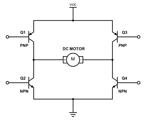
H Bridge Motor Driver Circuit Diagram Using Transistors
Components Required for H Bridge DC Motor Driver Circuit
- Resistors (100Ω x 4, 1kΩ x 2)
- Switches x 2
- Transistors (NPN x 2, PNP x 2)
- Load (DC Motor)
Simulation | Animation | Working Principle of H Bridge DC Motor Driver Circuit
We know how a transistor acts as a switch. The switching property of NPN and PNP transistors are used in the H bridge motor driver circuit.
- Refer to the circuit diagram. When SW1 is closed 0V appears at the base of Q1 and Q3.
- Then transistor Q3 turns ON. Since it is a PNP BJT, it needs a LOW voltage to turn ON.
- But transistor Q1 remains OFF. Because it is NPN and requires HIGH potential at the base to turn ON.
- SW2 is not closed so transistor Q2 may remain ON. And transistor Q4 is OFF because HIGH potential appears at the base terminals.
- So a current path exists via Q3-> motor-> Q2. So the motor rotates in a particular direction (say clockwise direction).
- Consider SW2 is closed and SW1 is open, similarly Q4 and Q1 are ON and Q3 and Q2 are OFF.
- Then the current path is reversed which is Q4-> motor ->Q1. This allows rotating the motor in the opposite direction (anti-clockwise direction).
- Thus, an H bridge driver can effectively control the rotation of themotor in both directions.
- If both inputs are simultaneously HIGH or LOW, then the Motor is at Rest.
Please have a look at the simulation/ animation of the H bridge driver circuit.
Table Showing the Working Principle of the Motor Driver
| SW1 | SW2 | Q1 | Q2 | Q3 | Q4 | Direction |
| 0 | 0 | OFF | OFF | ON | ON | Rest |
| 0 | 1 | OFF | ON | ON | OFF | Clockwise |
| 1 | 0 | ON | OFF | OFF | ON | Anticlockwise |
| 1 | 1 | ON | ON | OFF | OFF | Rest |
Table of Working Principles of H Bridge Motor Driver Circuit
Transistor Pin Out
Thanks to components101.com
Entering into the realm of robotics requires controlled locomotion of the moveable parts, cluster wheels are at the top of the choice list, and there’s no better alternative to using an H-bridge motor driver to drive your DC motors. Thus, implementing an H-bridge motor driver circuit using transistors is the best option.
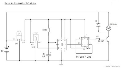
2. Remote Controlled DC Motor Circuit Diagram
Remote Controlled DC Motor is important for most projects where moving parts are required. To make projects with remote-controlled DC motors, you’ll need a simple, and easy-to-fabricate circuit diagram. So, let’s start with the circuit diagram first.
Components
- 9V Battery
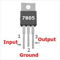
- 7805 voltage regulator
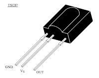
- TSOP IR receiver
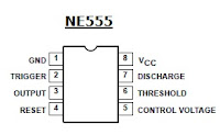
- IC 555
- IC 7474
- BC 548
- Diode 1N4007
- Resistors (220KΩ, 100Ω)
- Capacitor (1μF)
- DC Motor
Working
- The maximum voltage of TSOP and 7474 is 5v. So we are using a 7805 voltage regulator IC. Its output is 5V
- The output of TSOP is always 5V, and the output will be zero when IR rays strike on it
- 555 biased as a Monostable multivibrator. Normally its output is 0V, provided that voltage at the 2nd pin must be greater than 1/3Vcc
- When the voltage at the 2nd pin goes below 1/3Vcc output switches to high (5V) for the time T=1.1RC after the time interval output returns to 0V
- 7474 is a D-flip flop. It is wired in Toggle mode. i.e Q’ to D input. 555 used as a clock generator
- When it gets a clock pulse Output goes High and remains in that state till the next pulse
- On receiving the next pulse output goes to low and remains in that state till the next pulse
- This process will continue. The output of 7474 is fed to the base terminal of BC 548
- BC 548 is a driver transistor, when its base voltage is high current will flow through the load
- Here Our DC motor the load and it will rotate only when the base voltage is high
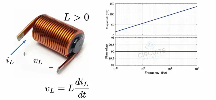
- Diode Df is a freewheeling diode used to dissipate the stored energy in the inductor load
Components Pinout
DC motor is one of the most important of any project no matter what big or small. Using a remote-controlled DC motor, you can make your project handier and more attractive. With this circuit diagram, you can easily build your own remote-controlled DC motor.
3. Bidirectional Motor Control (Driver) Circuit for Robotics Beginners Using l293d IC
We have already discussed the H Bridge motor driver circuit with the transistors above. So, as you know the working procedures of H Bridge, let’s discuss the bidirectional DC motor control circuits.
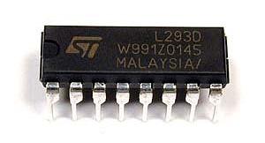
You may already know that the L293D IC is widely used for implementing DC motor control circuits. It is a dual H bridge motor driver IC that can drive two DC motors simultaneously and can be found in 16 pin DIP package.
L293 driver IC has a current capacity of 600mA per channel and a wide supply voltage range (4.5 to 36V DC). They are integrated with internal high-speed clamp diodes for inductive spike protection. Other superior features of L293 are high noise immunity, internal ESD protection, thermal shutdown, and a separate input supply for each channel.
Now, let’s get started with the Bidirectional Motor Control (Driver) Circuit.
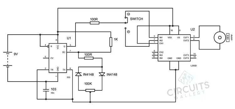
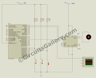
Circuit Diagram of l293 Motor Driver

Components required for DC motor driver
- Power supply
- L293 Motor driver IC
- DC Motor (5V, 250mA)
- Switches x 4 Resistors (1kΩ x 4)
Working L293 driver circuit
- To understand the working principle of the L293 driver IC circuit you must read the What is H bridge? Article
- L293 IC can drive two DC motors simultaneously. Each output has its own Enable pin (EA for Motor 1, EB for Motor 2).
- If EA or EB is zero (low voltage), the corresponding DC motor is free to move on its shafts.
- After giving 1 (High voltage) to the Enable pin, we can control the direction of rotation of DC motors by digital manipulation of the inputs.
- For each motor, there will be two inputs (for Motor 1 inputs are A1 and A2 similar to B1 and B2 for Motor 2).
- If both inputs are 0 or 1, the DC motor in the shaft is locked or baked.
- An alternate input combination will drive the motor in either direction.
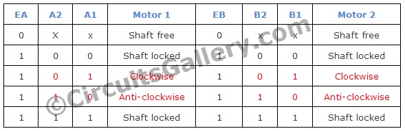
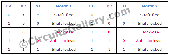
- Please refer to the below table, it shows possible input combinations and the direction of each motor.
| EA | A2 | A1 | Motor 1 | EB | B2 | B1 | Motor 2 |
| 0 | X | x | Shaft free | 0 | x | x | Shaft free |
| 1 | 0 | 0 | Shaft locked | 1 | 0 | 0 | Shaft locked |
| 1 | 0 | 1 | Clockwise | 1 | 0 | 1 | Clockwise |
| 1 | 1 | 0 | Anti-clockwise | 1 | 1 | 0 | Anti-clockwise |
| 1 | 1 | 1 | Shaft locked | 1 | 1 | 1 | Shaft locked |
- In our circuit we applied A2=0, A1=1; B2=0, B1=1 using a pull-down resistor switch arrangement. Hence both motors will rotate in a clockwise direction.
- You can make a simple robot with this driver circuit. It can move forward, backward, and turn left and right. Keep in mind the maximum current capacity of L293D is 600mA so don’t use DC motors that consume more than 600mA current.
Here we have got a brief idea about the L293D driver. It is a versatile component that can be used to control any small or large electrical components by controlling the direction of current flow.
4. Servo Motor Control using Microcontroller PIC16F877A
The Servo Motors can be controlled by PWM signals where the required angle of rotation can be located by a particular PWM signal. They have an output shaft that is connected to an arm and the mechanical connections are attached to this arm, which can rotate a maximum of 180 degrees.
It has three connection wires: V positive, V negative, and control signal. The signal is normally connected with microcontrollers to feed the PWM signal as required. The position of the servo arm is determined by the PWM signal:
- 1500µs for servo neutral position.
- If the signal is less than 1500µs then the arm moves back to a particular angle (anti-clockwise).
- If the signal value is greater than 1500µs then the arm moves clockwise to a particular angle depending on the signal value.
PWM of 1000µS will move the arm to zero position which is the minimum position and 2000µS will move the arm to the maximum.
The Servo motor has also an inbuilt control circuit to convert the PWM signal to the position value, it has a movable potentiometer that is used to locate the position by a balancing mechanism.
Now, let’s see in detail about the PWM servo control and how to control the servo motor using pic16f877a.
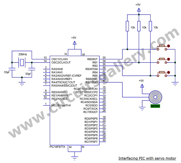
Servo motor control circuit
Components Required
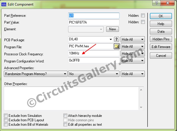
- PIC16F877A
- Crystal 20MHz
- Capacitor (33pf x 2)
- Resistor (10K x 3)
- Servo motor
- Push buttons x 3
Working
- Here I use three switches to rotate the arm to -90 degrees (minimum position), zero degrees, and +90 degrees.
- The arm rotates these three positions by pressing the switches.
- The application of this in a robot is to turn the front wheel by pressing the buttons on the remote, but here rotation is 90 degrees so you have to minimize this by changing the PWM signal.
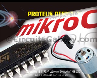
- Here we have used the mikroC compiler.
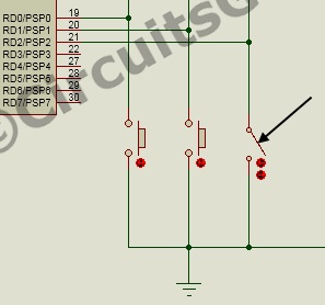
- Port B is used to connect the servo motor and controlling switch, the controlling switches are connected to +5V through a 10K (called a pull-up) resistor.
- The control signal of a servo motor is connected to the 7th bit of the port and switches are connected to the 0th, 1st, and 2nd pins of PORTB.
- Three sub-functions are used to move the arm left, straight, and right for the -90, 0, and +90 rotations.
- In the main function, there is an infinite loop that continuously checks the 0, 1, and 2nd pins of PORTB.
- If any switch gets a negative signal when pressing the button then the program control is changed to the sub-function for the particular switch, and it returns back to the infinite loop.
Servo motor PIC Program
[cc lang=”C”]
void left();
void right();
void stright();
int i;
void left()
{
for(i=0;i<10;i++)
{
PORTB.F7 = 1;
Delay_us(500); //500us Delay
PORTB.F7 = 0;
delay_ms(80); //800us delay } }
void right()
{
for(i=0;i<10;i++)
{
PORTB.F7 = 1;
Delay_us(2500); //2500us Delay
PORTB.F7 = 0; delay_ms(80); //800ms delay
}
}
void stright()
{
for(i=0;i<10;i++)
{
PORTB.F7 = 1;
Delay_us(1500);//1ms Delay
PORTB.F7 = 0; delay_ms(80);
}
}
void main()
{
TRISB =0B00001111; //PORTB as Output and Input Port
while(1)
{
if (portb.f0==0)
{
right();
}
else if (portb.f2==0)
{
left();
}
else if (portb.f1==0)
{
stright();
}
}
}
[/cc]
The Servo motor is an important component of many electronic projects. As so, controlling this motor is vital which can easily be done by following the above process. We’ve also provided the code for you that can be implemented within seconds.
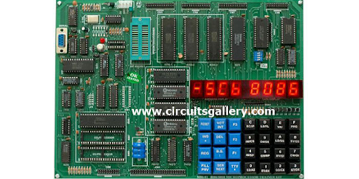
5. How to Program Stepper Motor in Microprocessor 8086 Assembly Language
We are going to help you create a stepper motor controller using an 8086 microprocessor and 8255 Programmable Peripheral Interface IC in this section.
This stepper motor assembly language program is quite simple & easy, and we’ll use this language to program the 8086 microprocessor here. Here we described the functions of each code for better understanding.
Notations used For representing different types of numbers
We are using some notations here.
B: – used to indicate Binary Number
H: – used to represent Hexa Decimal Number
CW used to represent the Control Word register
You must know!
- The Stepper motor is interfaced to 8086 with the help of 8255 IC (Programmable Peripheral Interface).
- 8255 has two modes of operation BSR (Bit Set Reset) mode & IO (Input Output) mode.
- The mode is determined by the Control Word (CW) register; (here the CW address is 26).
- Initialize the CW with (0000 0000)B=(00)H for BSR mode & (1000 0000)B=(80)H for IO mode
- The Stepper motor is an IO device so CW should be (80)H There are 4 poles in a typical stepper motor A1, A2, B1, B2
- To energize the poles for anticlockwise rotation we have to apply the following to the poles
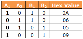
So we, out these set of values to the IO port of 8255
8086 Assembly Language Programming Code for Beginners
The below program shows the interfacing of the Stepper motor
1000 MOV AL,80 /*Move 80(hex) to AL*/
1002 OUT 26,AL /*Move 80(Hex) to PPI, 26 is the CW of PPI*/
1004 MOV AL,0A /*Energizing the poles*/
1006 OUT 20,AL
1008 CALL 2000 /*Give some delay to rotate Motor*/
1010 MOV AL,06
1012 OUT 20,AL
1014 CALL 2000
1016 MOV AL,05
1018 OUT 20,AL
1020 CALL 2000
1022 MOV AL,09
1024 OUT 20,AL
1026 CALL 2000
1028 JMP 1004 /*Repeat the steps*/
1030 HLT
In the memory location 2000, we should give Delay program. You can choose any memory location other than 2000 as you like.
The delay Program is shown below
2000 MOV BX,1000 /*Move a value to BX*/
2002 DEC BX /*Decrementing the value*/s
2004 MP BX,0000 /*Check whether the value reach 0000*/
2006 JNZ 2002 /*If not 0000, Decrement again*/
2008 RET /*Return to the Motor program*/
Programming 8086 is not an easy thing, but you can do it by following the above procedures. Here we have given you the code and explanation of how to program a stepper motor on an 8086 Microprocessor.
6. DC Motor Interfacing With Pic Microcontroller Using l293 Motor Driver IC
L293d is an H Bridge bidirectional motor driver IC used to interface DC motor and stepper motors to Microcontrollers. You can easily make a DC motor control using a microcontroller.
Basically, it is a bidirectional motor driver circuit with PIC MCU. This is the most common circuit in robotics engineering.
In this section, we’re going to show you the interfacing of a DC motor with a PIC16F877A microcontroller using an L293D motor driver with the help of Micro C coding and Proteus 8 simulation. We hope, this section will be helpful for you as a PIC MCU beginner.
What is H Bridge?
H bridges are a widely discussed topic in electronics. As we know, just changing the polarity of the supply voltage causes the rotating of the DC motor in the reverse direction. But this method is not suitable for practical circuits. So, how to run the DC motor in clockwise and anti-clockwise directions without changing the supply polarity?
Here comes the importance of H Bridge. In a typical H Bridge circuit, two pairs of transistors are connected in a bridge fashion and the motor is driven through the collector terminal.
Why L293?
Obviously, we know that ICs make life easy!
- The transistor-based H bridges are a little complex and bulky and also time-consuming while implemented practically.
- L293 is basically an H bridge IC capable of driving two motors simultaneously, which means it has two embedded H bridges inside!
Interfacing L293 with the DC motor and microcontroller is a very easy and simple process.
The specialty of L293 is that it has a dedicated ‘Enable Pin’ to control the motor. By manipulating this pin it is possible to control the speed of the DC motor with Pulse Width Modulation technology.
Schematic Diagram
Components Required
- PIC16F877A
- L293d
- DC Motor
Tools Required
- Mikro C Pro
- Proteus design suite
Mikro C Code for DC Motor Interface
The Switch at PORTD.F2 is responsible for the direction changing of the motor. We have also used the PWM speed-controlling method here in order to use this program for the further development of robotics.
Program Logic
- We are applying 0×01 = 0000 0001 and 0×02 = 0000 0010 to the input pin of the L293 driver IS using a microcontroller.
- According to these inputs, the direction of the motor will change. (Refer to the below table to understand the basic configurations of L293 IC).
Program
void main()
{ short duty1 = 16; //Initial value for duty
TRISD = 0xFF; //PORTD as input
TRISC = 0x00; //PORTC as output
TRISB = 0x00; //PORTB as output
PWM1_Init(1000); //Initialize PWM1
PWM1_Start(); //start PWM1
PWM1_Set_Duty(duty1); //Set current duty for PWM1
while (1) //Endless loop
{
if (PORTD.F2==0)
{ PORTB = 0x02; //Run motor in anti-clockwise
}
if (PORTD.F2==1)
{ PORTB = 0x01; //Run motor in clockwise
}
if (PORTD.F0==0) //Checking the button pressed or not
{ Delay_ms(1); duty1++; //Increment duty cycle
PWM1_Set_Duty(duty1); //Change the duty cycle
}
if (PORTD.F1==0) //Checking the button pressed or not
{ Delay_ms(1);
duty1–; //Decrement duty cycle
PWM1_Set_Duty(duty1);
}
Delay_ms(10);
} }
Program Simulation in Proteus 8
Step 1 Write the above C codes in Mikro C and build.Hex fie.
Step 2
Run Proteus 8 and draw the schematic DC motor interface with PIC
Step 3
Load.Hex file to PIC MCU by double-clicking on the IC.
Step 4
Now it’s time to simulate… Run

Step 5
Change the switch positions at PORTD.F2 and observe the bidirectional rotation.
We have given you a full overview of DC motor interfacing using L293 motor driver IC. We also have provided the required code and have shown a step-by-step process on how to simulate the process using the software.
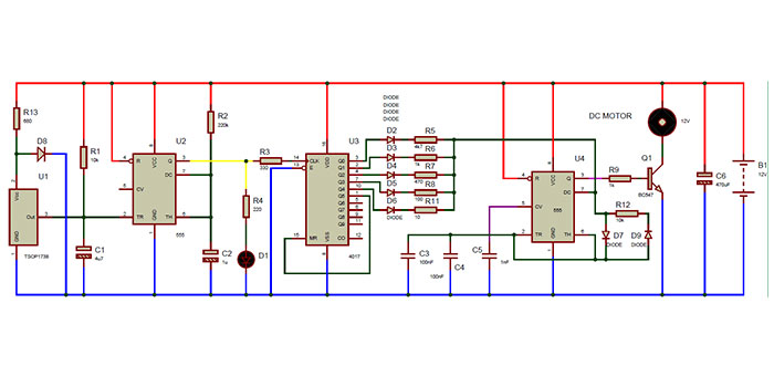
7. Remote Controlled DC Motor for Toy Car Circuit Diagram
Here we are going to work with a simple circuit of a remote-controlled toy car. The main component used here is the IR sensor circuit consisting of TSOP with which, we can start and stop the DC motor vehicle.
However, this circuit has a small disadvantage that it can’t control the speed of the DC car motor, rather it turns ON and OFF the small DC motors. Once it is ON, the motor runs at a constant speed. No circuits for controlling the speed are discussed here.
To do this project, you’ll need a regulated power supply of 5 volts to do this one because TSOP requires 5v for its operation. Here we have discussed the circuit diagram and working of remote controlled DC motor for a car using a T sop infrared detector circuit.
The advanced version of this circuit with the PWM speed controller will be posted soon. Till then, let’s explore this beginner’s circuit below.
Circuit Diagram of Remote Motor Controller
Components Required
- 9V Battery
- 7805 voltage regulator
- TSOP IR receiver
- IC 555
- IC 7474
- BC 548 Diode
- 1N4007
- Resistors (220KΩ, 100Ω)
- Capacitor (1μF)
- DC Motor
Circuit Working
- The maximum voltage of TSOP and 7474 is 5v. So we are using a 7805 voltage regulator IC which provides 5V output.
- The output of TSOP is always 5V, and the output will be zero when IR rays strike it.
- 555 timer IC is biased as a monostable multivibrator. Normally its output is 0V, provided that voltage at the 2nd pin must be greater than 1/3Vcc
- When the voltage at the 2nd pin goes below 1/3Vcc, the output switches to high (5V) for the time interval T=1.1RC. After this time interval output returns to 0V.
- 7474 is a D-flip flop. It is wired in Toggle mode. i.e Q’ to D input. 555 is used as a clock generator here.
- When it gets a clock pulse output goes high and remains in that state till the next pulse.
- On receiving the next pulse output goes low and remains in that state till the next pulse.
- This process will continue. The output of 7474 is fed to the base terminal of BC 548/BC 187.
- BC 548 is a driver transistor, when its base voltage is high current will flow through the load.
- Here DC motor is the load and it will rotate only when the base voltage is high.
- Diode Df is a freewheeling diode used to dissipate the stored energy in the inductor load.
DC motor is one of the most used components for small prototypes and projects. We hope, now you know how it works after reading this section.
Conclusion
DC motor projects are basic electronic projects for beginners. All the basic and advanced DC motor driver control circuit-based projects are demonstrated in this article, and we hope, now you can make your very own Robotics engineering and automation projects using some simple and cheap ICs after reading this guide. If you have any confusion on any projects, then don’t hesitate to ask in our comment section below. Thanks for reading and best wishes for your upcoming project.
- 1. H Bridge Motor Driver Circuit Using Transistors | Theory & Practical
- 2. Remote Controlled DC Motor Circuit Diagram
- 3. Bidirectional Motor Control (Driver) Circuit for Robotics Beginners Using l293d IC
- 4. Servo Motor Control using Microcontroller PIC16F877A
- 5. How to Program Stepper Motor in Microprocessor 8086 Assembly Language
- 6. DC Motor Interfacing With Pic Microcontroller Using l293 Motor Driver IC
- 7. Remote Controlled DC Motor for Toy Car Circuit Diagram
- Conclusion
Subscribe to our newsletter
& plug into
the world of circuits