What Is Hexa Decimal? Why It Is Used in Microcontrollers?
What is Hexadecimal? Hexadecimal numbers are used in Microcontrollers, Microprocessors, etc. The term Hexa Decimal indicates that Hexa – (six) plus Decimal (ten), i.e. Sixteen. The base 16 number system is called Hexadecimal. At the very launch of computer expansion, it was realized that people had many complexities in managing binary numbers. For this reason, a new number system using 16 different symbols was developed. It is called a hexadecimal number system and consists of the ten digits and 6 alphabets, i.e. (0, 1, 2, 3, …. 9, A, B, C, D, E, and F). In this article, we will cover why hexadecimal is used? binary to hexadecimal conversion and hexadecimal to the decimal conversion table.
Need & Importance of Hexadecimal Number Systems
Long before, programmers commonly used a suitable method to handle large binary numbers in 4-bit groupings. It is easy to manipulate large binary numbers if we group them into small groups consisting of 4 bits per group.
For example consider you are dealing with the binary number 0011010110000111, if we group this number to 4-bit clusters like 0011 0101 1000 0111 then write the corresponding single-digit decimal value, the processing is quite easy.
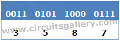
Thus, 0011010110000111=3587.
What Happens After 9?
While following the above-said method there is a discontinuity that arises after decimal 9. That is how to write decimal corresponding to 1010?
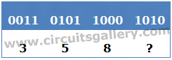
Binary 1010 = Decimal 10, it has 2 digits! Here comes the importance of alphabets…! That is after 9 we use the alphabets A, B, C, D, E, and F for coding. Thus it again retains single-digit up to the number 1111.
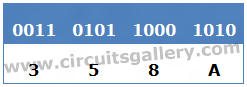
i.e 0011 0101 1000 1010 = 358A
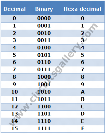
Decimal Binary Hexadecimal Converter Table
Why Hexadecimal? How It Helps Microcontroller Programming
The biggest binary number that can be characterized by 4 binary digits is the number 1111. It corresponds to the number 15 in the decimal system, whereas in the hexadecimal system it can be represented by only one digit i.e ‘F’. It is the largest 1-digit number in the hexadecimal system. In 8 bit PIC microcontroller the largest number is 1111 1111 has 8 bits is at the same time the 2 digit hexadecimal number for 1111 1111 is ‘FF’. Do you see how skillfully it is used? Don’t forget that computers process 8-digit binary numbers. For the convenient use of programmers, it is easy to manipulate hexadecimal numbers rather than binary numbers. Hexadecimal numbers are represented in the C language by using the prefix ‘0x’.
Eg: 0x25, 0x85 etc.
Hexadecimal in Pic [Real Time Example]
Consider the embedded C program code,
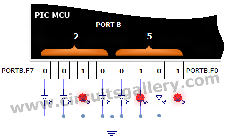
PORTB=0x25;
0x25= 0010 0101
Then the corresponding pins of PORT B are set to logic high, we can connect LEDs for checking the status. See the image below.
Embedded C Program to Realize Hexadecimal
void main()
{
TRISB=0x00;
while(1)
{
PORTB=0x4D;
delay_ms(1000);
PORTB=0xAF;
delay_ms(1000);
}
}
Here we are outing 0x4D and 0xAF to the PORT B continuously with an interval of 1 second. To understand the concept of Hexadecimal in this program, please watch the following PIC simulation.
Conclusion
Hopefully, by this time, you have got a clear picture of the hexadecimal number system and why this is used in microcontrollers. Though binary is used throughout the computational system, hexadecimal still rules in this realm.
Subscribe to our newsletter
& plug into
the world of circuits