How to Simulate PIC Microcontroller in Proteus Design Suite 8? | A Step-by-Step Guide
Right from the 1st PIC microcontroller PIC1650, this family of microcontrollers has won the hearts of millions among electronics enthusiasts and DIYers. Being the world’s smallest microcontroller series to carry out the most multifarious tasks, PIC has taken the core roles in innumerable projects.
Thus the importance of simulation of PIC microcontroller knows no bounds before you take the practical implementation of any project where it’s involved.
Any simulation software can interact with the embedded project with screen indicators for example LED, LCD displays, switches, and buttons. The simulation takes place in real-time. Even rotating appliances like induction motors can also be simulated. Obviously, in this case, only the required data is shown. For instance RPM, torque, etc.
As Circuits Gallery covers the topic of Microcontrollers, especially with PIC (Peripheral Interface Controller), this guide will show you how to simulate PIC in one of the best PIC microcontroller simulation software ‘Proteus Design Suite Version 8’.
Importance of Simulation of PIC Microcontroller
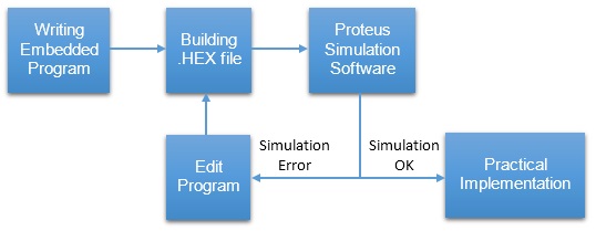
The goal of any simulation is the determination of the most feasible means. Especially in cases of electronics, before going to the practical implementation of the circuit it’s always the best practice to test whether the embedded program will work perfectly for our project.
The importance of simulation software is highlighted below. Such software provides an environment to test our microcontroller program.
It is possible to play with your microcontroller just as in the real world. In this article, we are going to deal with the most powerful simulation software – the Proteus Design Suite Version 8.
What Is Proteus VSM?
Proteus Virtual System Modelling (VSM) has mixed-mode SPICE circuit simulation, animated components, and microprocessor models to ease co-simulation of complete microcontroller-based designs.
Over ten years later, Proteus VSM is still primary in the arena with more microcontroller variants and peripherals than any competing product, top debugging tools and instruments, and a consistent focus on innovation.
What Can You Do with Proteus Simulation Software?
Proteus brings you total freedom to experiment with diverse ideas and to discover the optimal design solution for our project.
- Alter your ‘hardware’ by rewiring the circuit diagram, varying component values for resistors, capacitors etc.
- Removing or making new components to the design.
- You can change your firmware in the IDE of your choice and, once compiled, test the new code on the new system at the press of a button.
- Reprogramming microcontroller: In practical there is limitation to flash the memory of microcontroller but in Proteus you can burn program unlimited times.
- Attain confident that your program will work for real world applications.
The schematic serves as a ‘virtual prototype for the firmware and it’s quick and easy to make changes to either.
Advantages of Simulation using Proteus VSM Lab
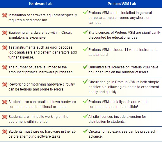
Image credit: www.labcenter.com
Steps for Simulating PIC Microcontroller in Proteus Design Suit 8
In this tutorial, I’ve already built the .HEX file of the LED blinking program. The only pre-requisite is that you know how to build .hex file. Next, we are gonna proceed towards how to simulate the PIC16F877A microcontroller using Proteus.
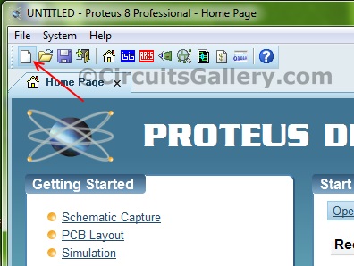
Step 1 Create a New Project
Click the New Project button.
Now give a name to our project
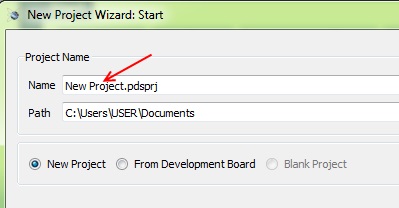
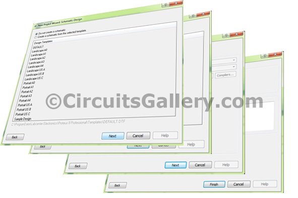
Do not change anything, just follow the default options and click Next until you see the Finish button.
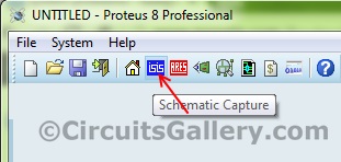
Step 2: Draw the circuit diagram that simulates the PIC microcontroller project
Now click the Schematic Capture button, you will be directed to the schematic panel.
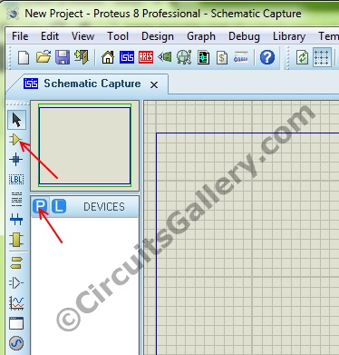
Step 3: Add components to workspace
Click the P button followed by the Component button under Devices for picking components
Step 4: Choose your component
Simply type the name in the Keywords box. After selecting the item click OK.
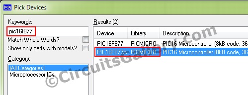
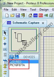
The selected components will be listed under Devices.
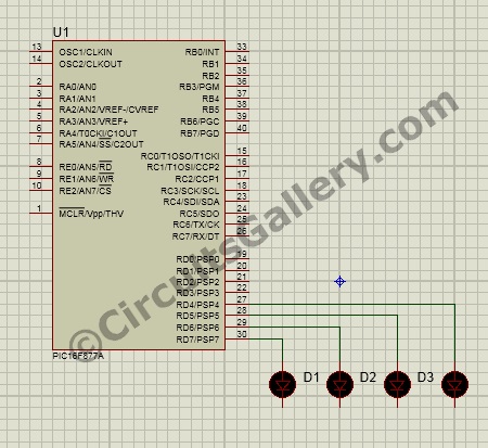
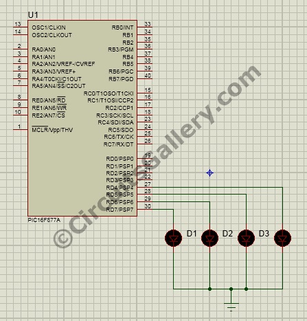
Step 5: Implement the circuit of LED blinking
Now draw the circuit diagram as shown below.
Step 6: Where is the ground terminal in Proteus 8
Click the Terminal mode button to get different terminals
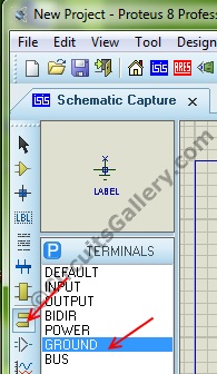
Click Ground and add to our schematic.
Step 7: Set the Memory clear pin to high
Apply MCRL signal to PIC MCU, Click the Generator mode button, and choose DC.
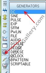
Connect it as shown below diagram.
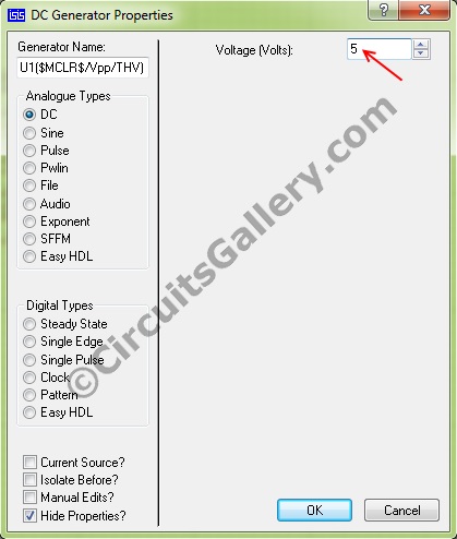
Double click on the DC terminal and set its voltage as 5.
That’s all our basic connections for the simulation.
Step 8: Set clock frequency to PIC MCU in Proteus
Double click on the PIC IC, the Edit component wizard will open. Set the frequency as the same as that you did for generating .HEX file. (I compiled my embedded program at 10MHz frequency. Hence I selected 10MHz here).
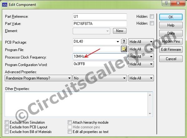
Keep rest options as default.
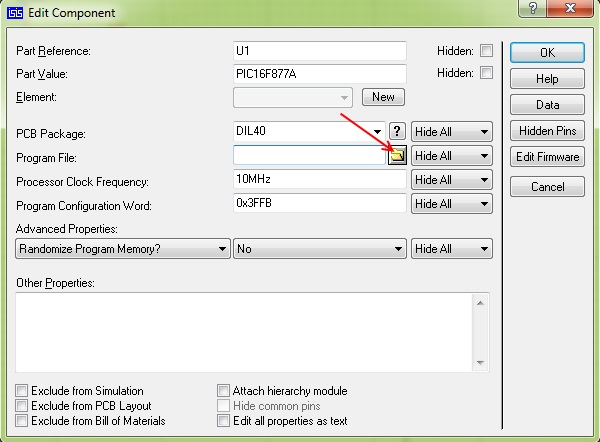
Step 9: Load .HEX file to the schematic diagram of PIC
After setting frequency click the browse button to load the .HEX file.
Choose your .HEX file
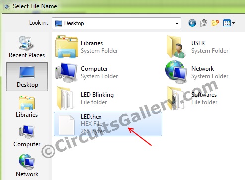
Finally, click OK. Now everything is ready to go.
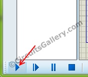
Step 9: Let’s run the simulation PIC Microcontroller in Proteus…!
Click the Run Simulation button at the bottom left corner and observe your PIC simulation.
Yes, now you have successfully simulated your PIC project. Play more and more and explore your Virtual lab…

Conclusion
Though it was just the simulation of a very basic project, the article shed light on almost all the main aspects of simulation in Proteus. If you can master the whole procedure, simulating any project using Proteus will be a moment’s job. So, clearly, it covered more than how to simulate PIC microcontroller.
Subscribe to our newsletter
& plug into
the world of circuits