How to Make A 75 To 300 Ohm Matching Transformer? | A Step by Step Guide for You
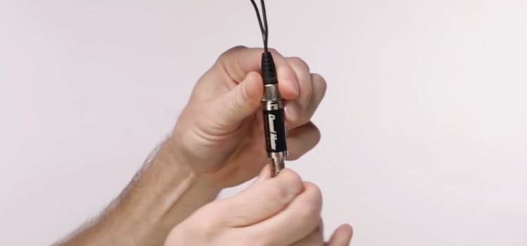
By wrapping some wires around a toroidal core, you can make a 75 to 300 Ohm matching transformer. It will cost you no more than $5. It will cost you nothing if you can find a few copper wires and…