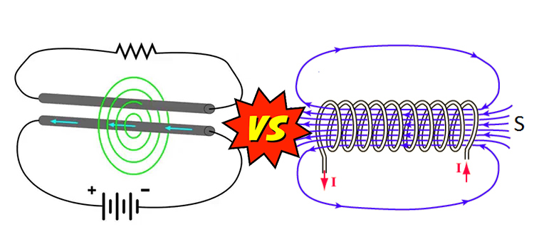
Impedance vs Inductance
Impedance and inductance have a specific and different impact during the flow of current in a particular circuit depending on passive elements present in that circuit.
Impedance is a measurement of a circuit’s total opposition to electric current including both resistance and reactance. Whereas inductance is the property of an electric conductor or appliance by which the change in current produces an electromotive force.
Impedance vs Inductance
Impedance (symbol Z) determines how much the overall circuit obstructs the flow of charge. It’s similar to resistance in DC circuits. But in AC circuits, where there is a change in voltage and current, it also takes the effect of capacitance and inductance into account.
So, inductance (symbol L) may be considered as a part of the total impedance of a particular circuit as it is included in form of inductive reactance (XL=ꞶL), where impedance, Z=R + j XL. (R=resistance).
Impedance
The impedance of the circuit or the circuit element is defined as the ratio of the phasor voltage across a passive circuit element to the phasor current through the circuit element.
Impedance, Z=V/I
Here, V = voltage in volts (V)
I = current in amps (A)
Z = impedance in ohms (Ω)
Impedance is a two-part complex number the real part and the imaginary part:
Z = R + j X
Z denotes complex impedance. The real portion, R = resistance. While the imaginary portion, X = reactance.
Resistance is always positive and constant regardless of frequency. On the other hand, reactance can be either positive or negative and varies with frequency due to capacitance and inductance.
Reactance
Reactance (symbol X) is known as the opposition produced by the capacitor and inductor in a circuit to the flow of AC. Reactance is comparable to resistance, except it fluctuates depending on the frequency of the ac voltage source.
Inductive Reactance
Inductive reactance is the opposition caused by the inductor of an AC circuit which opposes the passage of current. It is represented by (XL) and measured in ohms (Ω). It is proportional to frequencies. The formula is:
Inductive reactance, XL = 2πf L
Where, f = frequency of AC voltage source (Hz)
L = inductance (H)
Impedance Triangle
It is a representation of circuit impedance in terms of geometry. We discussed that, impedance can be expressed by, Z = R + j X
Since Z is a complex number, it can be geometrically represented in the same manner as a complex number. The geometrical representation is shown below:
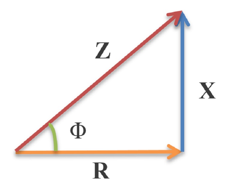
The above triangle is called the impedance triangle. The magnitude of impedance Z,
Z2 = R2+X2
The angle which Z makes with R can be found as,
tan Φ = (X/R)
Power Factor
The impedance triangle helps us to determine the power factor. Power factor is equal to the cosine of the angle between Z and R,
Pf= cos Φ = (R/Z)
Inductance
Inductance represents the physical property or ability of a circuit element to produce magnetic flux linkage in response to current. It is represented by the letter L, and Henry is its unit. The inductor is a circuit device that is specifically intended to do this job.
An electric current flowing through a coil produces a magnetic field around it. Changing this magnetic field induces an electromotive force. According to Faraday’s law of induction,
The electromotive force or voltage (VL) across the coil is proportional to the rate of change of the current through it,
VL ∝ di / dt
VL = L di/dt
L is the constant of proportionality. The value of L is independent of the voltage across the inductor and the current through it.
Again, the inductance L of a coil depends on the core material and its physical dimensions and is given by
L=Nφ/I=μN 2Al, φ is the magnetic flux in the core, μ is the permeability of the core material, A is the cross-sectional area of the core, and l is the mean length of the flux path through the core.
The Impedance of an Inductor
The impedance of an inductor is denoted by ZL, ZL= jꞶL, where ꞶL is the reactance of the inductor, XL
Inductors are used to lag the current by 90 degrees compared to the voltage.
Frequently Asked Questions
Is impedance an inductive quantity?
Impedance is a vector quantity. There can be resistive, inductive, and capacitive elements in a circuit. Impedance represents all the opposition caused by both resistance and reactance.
Conclusion
The terms impedance and inductance may seem similar but they have individual properties in case of operating in an electrical circuit. Impedance denotes the overall opposition during current conduction and inductance is simply a property of an electric circuit in which a change in current induces an electromotive force.
Subscribe to our newsletter
& plug into
the world of circuits

![[Explained] How Many Valence Electrons Does a Conductor Generally Have?](https://www.circuitsgallery.com/wp-content/uploads/2023/11/How-Many-Valence-Electrons-Does-a-Conductor-Generally-Have.webp)
Very good description of the basic and fundamental electrical and electronic principles/concepts for the hobby reader or student/professional.
I find this site very educational and concise with easy to understand language and pictorial representations. This site is what I’ve sought.
Thank you for your positive feedback! We’re delighted to hear that you found our site’s description of electrical and electronic principles both informative and accessible.If you have any further questions or topics you’d like us to cover, please don’t hesitate to reach out. We’re here to support your learning journey!