Condenser Microphone Amplifier Schematic Using BEL 1895 IC
Here I will show you an audio amplifier circuit that can be used for walkie-talkies, low-power transmitters, and packet radio receivers. A condenser mic audio amplifier gives good quality audio of 0.5 watts at 3 volts. Here we are going to make use of BEL 1895 (Bharat Electronics Limited 1895) audio amplifier IC which is also a noise-free amplifier IC. We are also using a preamplifier section here to boost the weak signal from the condenser mic. The pre-amplified signal is connected to BEL 1895 audio amplifier IC. The preset in the first transistor acts as a gain controller, it can vary the gain of the amplifier circuit. PCB layout is also given below.
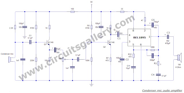
Circuit Diagram
Components Required
- Condenser mic
- Speaker
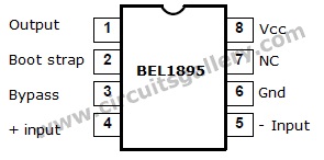
- BEL 1895 IC
- Resistors (2.2kΩ, 470kΩ x2, 470Ω x2, 47kΩ, 33Ω, 1Ω, 1kΩ x2, 100kΩ, 220kΩ, 100Ωx2)
- Preset 10kΩ
- Capacitors (100µF x2, 0.1µF x3, 47µF, 10µF x3, 150µF, 470µF, 1nF x2, 33pF)
Working of BEL1895 Audio Apmplifier
- Transistors Q1 and Q2 form the condenser mic preamplifier. Resistor R1 provides the required bias for the condenser mic.
- The 10KΩ preset at the emitter of Q1 functions as gain control of the voice signal.
- In order to enlarge the audio power, the low-level audio output from the preamplifier stage is coupled to the audio power amplifier BEL1895 IC via coupling capacitor C1.
- BEL1895 exhibits low distortion and noise and operates over 3V-9V supply voltage, which makes it ideal for battery operation.
- It is a monolithic audio power amplifier IC intended particularly for sensitive AM and FM radio applications.
- Coupling capacitor C1 determines the low-frequency response of the amplifier. Capacitor C2 acts as the ripple rejection filter.
- Capacitor C3 connects the output to the loudspeaker. R1-C4 arrangement acts as the damping circuit for output oscillations. Capacitor C5 provides the bootstrapping function.
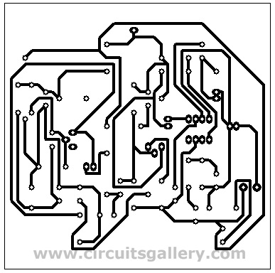
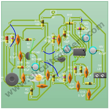
Pcb Layout of Audio Amplifier
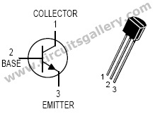
Components Pinout
Subscribe to our newsletter
& plug into
the world of circuits