How to Change a Circuit Breaker From 15 to 20 Amp
Yes, it is possible to upgrade or replace your 15 amp breaker with a 20 amp breaker, but several important factors require careful consideration. Simply swapping out the breaker without proper evaluation can lead to overheating of the wires concealed within your walls.
For comprehensive guidance on transitioning from a lower-rated circuit breaker to a higher one, this article is a valuable resource.
Concern Behind Changing the Breaker
You can’t simply replace a smaller circuit breaker with a larger one. You can upgrade a 15-amp circuit breaker to a 20-amp circuit breaker if your wiring is of the proper gauge.
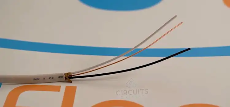
A 14-gauge wire is used in a 15-amp circuit. A 12-gauge wire is used in a 20-amp circuit breaker. You can use a 20A breaker instead of a 15A breaker if the copper cable is 12 AWG.
Replacing a 20-amp breaker with a 15-amp breaker could be a solution for a variety of electrical concerns, ranging from adding a 15-amp outlet to stopping a 15-amp breaker from tripping continuously. Upgrading a dedicated circuit breaker from 15 to 20 amps might not be a smart idea.
The Need for Changing
Circuit breakers are essential for preventing overloaded or overheated circuits by shutting down power as soon as they detect a problem. Due to a system malfunction, we occasionally need to replace our circuit breaker. All you have to do if one of your fuses trips is reset it, and you’ll be OK.
If your circuit breaker trips repeatedly, it could be due to an overloaded power system or a defective circuit breaker. You should then upgrade your circuit breaker or use significantly greater devices and electrical equipment in your home. If you plan to add other devices, you should think about this as well.
If your system is in good working order, your circuit breaker shouldn’t need to trip very often. A defective circuit breaker is not the cause of all faulty circuit breaker symptoms. Old and poor wiring can sometimes cause a circuit breaker to trip unexpectedly. In this instance, an electrical circuit tracer may be required.
Necessary Tools
Only a few basic tools and a replacement breaker are required to complete the task. If the branch circuit has a 14-gauge wire, you’ll need to replace it with a new 12-gauge wire before installing a 20-amp breaker in the switchboard and a 20-amp outlet at the circuit’s end. The following are the tools you’ll need for the job.
- Gloves that are insulated, ideally rubber, for added protection.
- A screwdriver with a flathead
- A multimeter or a non-contact voltage meter
- Wire of 12 gauge
- A headlamp to provide additional lighting
Steps for Replacing the Circuit Breaker
Here are the steps listed below to guide you in the changing process.
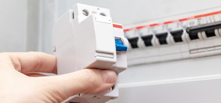
Step 1: Locate Your Circuit Breaker Panel
Wear your rubber gloves and unscrew the cover of your panel to access the circuit breaker you ought to replace. Remove it with your screwdriver, making sure to secure the cover panel snugly in place before removing the final screw. It will not fall to the ground and be damaged as a result of this.
Step 2: Verify the Wire Gauge
Check the size of the wires in the breaker line you choose to change. To handle a 20-amp current, change it with a size #12 if it’s a #14. However, if it is already size #12, you can proceed to the following step.
Step 3: Remove the Breaker You Want to Replace and Disassemble
To be extra safe, turn off your main breaker and open your flashlight. Remove the screw from the circuit breaker you’d like to replace and draw the wire cautiously. Disassemble the panel board by pushing it to the side of your circuit breaker. Ensure that none of the wires are carrying any current with your multimeter or contactless volt-meter.
Step 4: Install a 20-amp Circuit Breaker
You can check your 20 amp circuit breaker with your multimeter before installing it to avoid the inconvenience of installing a defective circuit breaker. If your wires are ready, you can install a 20 amp circuit breaker by pushing it sideways and applying pressure.
Step 5: Replace the Breaker and Turn On the Main
Check all of your connections and circuit breakers, then switch them on and use a voltage meter or multimeter to measure each voltage. In this manner, you can see if your circuit breaker has any irregularities. Replace the circuit breaker panel cover after you’ve finished changing the circuit breaker.
After you’ve completed all of these measures, you should check your breaker panel regularly to ensure that no problems arise.
Frequently Asked Questions
Can I use a 14-gauge wire to install a 20-amp circuit breaker?
If the actual wiring is rated for a larger circuit breaker, you can install one on the circuit. For circuits that require less current, such as light circuits, the contractor who wired the house will typically utilize a lighter gauge wire. The 14-gauge wire used in these circuits is less expensive and easier to pull.
Can I replace a 15 amp breaker with a 30 amp breaker?
Generally, it’s not advisable to replace a 15 amp breaker with a 30 amp breaker. Breakers are designed to protect the wiring and electrical components in a circuit. Replacing a 15 amp breaker with a 30 amp breaker could overload the circuit, posing safety hazards.
What is the benefit of a 20 amp breaker?
The benefit of a 20 amp breaker is that it allows for a higher current flow in a circuit compared to a 15 amp breaker. This can support heavier electrical loads without tripping the breaker, making it suitable for circuits with increased power requirements.
How many amps is safe on a 20 amp breaker?
A 20 amp breaker is designed to handle a continuous load of up to 16-17 amps. It’s important not to consistently load a circuit to its maximum capacity, as it’s recommended to leave some headroom for safety. Therefore, it’s typically safe to run loads of up to around 16 amps on a 20 amp breaker to prevent overheating and nuisance trips.
Conclusion
While there are situations where grounding from the meter to the panel is not mandatory, it’s a practice that enhances electrical safety. Whether you need to ground your system depends on factors such as distance, local codes, electrical load, and safety considerations. When in doubt, consulting with a qualified electrician is a wise choice to ensure a secure and compliant electrical setup. Electrical systems are complex, and prioritizing safety is paramount.
Subscribe to our newsletter
& plug into
the world of circuits
![[Explained] Is Analog AC or DC?](https://www.circuitsgallery.com/wp-content/uploads/2023/08/Is-Analog-AC-or-DC.jpg)
![[Explained] How Long Does It Take a Capacitor to Discharge?](https://www.circuitsgallery.com/wp-content/uploads/2022/12/How-Long-Does-It-Take-a-Capacitor-to-Discharge.jpg)
How can you tell if the wire is 14 gauge, , or 12 gauge. When you say change the wire From 14 gauge to 12 gauge , what do you mean by that.
When someone mentions changing the wire from 14 gauge to 12 gauge, they are referring to replacing a wire that has a diameter corresponding to 14 AWG with a wire that has a larger diameter corresponding to 12 AWG.
A lower gauge number indicates a thicker wire that can handle a higher current capacity. So, switching from 14 gauge to 12 gauge means using a wire with a larger diameter capable of carrying more current.
How can I determine the wire gauge of the wire once it’s off the spool with a label? I have a micrometer – do you know the respective wire diameters?
To determine the wire gauge of a labeled wire off the spool using a micrometer, gently measure its diameter with the micrometer, then consult a wire gauge chart or conversion table to find the corresponding gauge based on the measured diameter in inches or millimeters, selecting the closest match for accurate identification.