6 Wire Voltage Regulator Wiring Diagram | A Comprehensive Guide
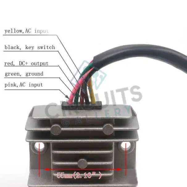
Connect the voltage regulator’s Black wire to a suitable chassis ground to wire a 6-wire voltage regulator. Connect the voltage regulator’s green wire to a switched +12VDC power source.
A rectifier or voltage regulator is a device that transforms alternating current (AC) to direct current (DC). This rectifier accepts 6V or 12V AC and transforms the output to DC. Connect the positive to the + terminal, the negative to the opposite terminal, and the two alternator leads to either side.
Wiring Diagram of 6 Wire Voltage Regulator
A 6-wire voltage regulator should be positioned from left to right on the shelf. Place the rectifier into the mounting slot after opening the rectifier handle (35 to 40-degree angle). Slide the rectifier till it reaches the back of the shelf. Push the rectifier handles towards the shelf to secure the rectifier.
The three terminals of a 6-wire voltage regulator are labeled input, common, and output for obvious reasons. The positive and negative supply terminals of the IC are simply linked across the input and common terminals, respectively. The controlled stabilized voltage is acquired.
Understanding the 6 Wire Voltage Regulator
The 6 wire voltage regulator is commonly found in various automotive and industrial applications. It features six wires, each with a specific function:
- Ignition (IGN): This wire is connected to the ignition switch and provides power to the regulator when the ignition is turned on.
- Battery (BAT): This wire connects to the battery and allows the regulator to monitor the battery voltage.
- Ground (GND): This wire is connected to the ground or chassis of the vehicle/machine, providing a reference point for the regulator.
- Field (FLD): This wire connects to the field terminal of the alternator or generator, controlling the current flow to the field winding.
- Stator (STA): This wire connects to the stator terminal of the alternator, providing a signal to the regulator to help it determine the output voltage.
- Auxiliary (AUX): This wire may be used for additional functions, such as connecting to warning lights or other auxiliary components.
How Is a Voltage Regulator Wired
We can acquire a controlled positive or negative voltage at any voltage we choose, depending on the voltage regulator in use. The LM78XX voltage regulators are popular for regulating and outputting positive voltage. The LM79XX voltage regulators are popular for controlling and outputting negative voltage.
The following image and steps will illustrate clearly how to wire a voltage regulator.
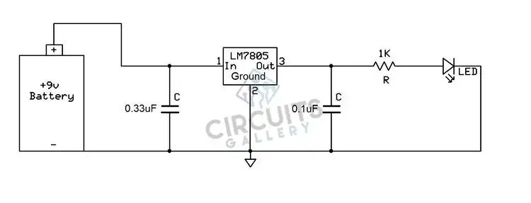
Step 1:
Connect the first capacitor, a 0.33uF ceramic capacitor, after the voltage source, in this example a 9-volt battery, and before the LM7805 regulator’s input. This capacitor serves to filter out any noise generated by the power source (the battery).
Step 2:
After the voltage regulator, connect the second capacitor, a 0.1uF ceramic capacitor. This capacitor is used to filter out any noise or high-frequency (ac) signals on the DC voltage line. It isn’t critical to have a pure DC signal in this circuit, where we’re lighting an LED.
Step 3:
Always reference the Manufacturer’s Datasheet for the voltage regulator being used in a circuit to determine how to connect it to the relevant external components. Typically, the only external components required are capacitors, though heat sinks may be required when heat dissipation is required.
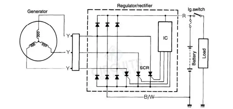
How Do You Wire a Regulator Rectifier
A regulator rectifier shall be wired according to the following figure:
The regulator rectifiers are charging control devices that correct the power output from the ACG, charge batteries, and maintain fixed battery voltages while not providing additional ACG output to the batteries.
Does Stator Wire Order Matter
The answer to the original query is simple: the Stator wires and the HOT / GROUND wires are irrelevant, but hot must go to hot and ground to ground (obviously), and there are two of each.
Ash, red, and black wires on the R/R are the DC output, hence the order is important in this case. Because the stator phase output wires are alternating current (AC), there is no polarity as there is with DC volts, therefore you can connect any stator output wire to any phase input to the R/R.
How Do You Install a Voltage Regulator
Perform the following steps to install a voltage regulator:
Step-1: Check that your new regulator is appropriate for the application. Each regulator is marked with the manufacturer’s name, voltage, and amperage. This regulator is suitable for both positive and negative ground electrical systems.
Step-2: When removing the wires from the old regulator, tape the terminal end of the battery wire temporarily. Tag the wires with the identification tags provided.
Step-3: Ascertain that the wires are connected to the correct terminal on the voltage regulator. Wire reversal can immediately destroy a new regulator or burn out the generator.
Step-4: Make sure there is good ground between the regulator base and the mounting surface. For rubber grommet-attached devices, this is performed by a ground strap on the base. Other models are bolted to the mounting surface. Before mounting, scrape the surface.
Step-by-Step Wiring Guide for a 6 Wire Voltage Regulator
Tools and Materials Needed:
- 6 wire voltage regulator
- Wiring harness
- Wire strippers
- Crimp connectors
- Electrical tape
- Multimeter
- Vehicle/machine wiring diagram (for reference)
Step 1: Safety First
Before starting any electrical work, ensure the vehicle or machine is turned off and the battery is disconnected to prevent any accidental short circuits or shocks.
Step 2: Identify the Wires
Using the wiring diagram for your specific vehicle or machine, identify each wire that will be connected to the voltage regulator. Label each wire if necessary to avoid confusion.
Step 3: Connect the Ignition Wire (IGN)
Locate the ignition wire in the wiring harness and connect it to the IGN terminal on the voltage regulator. This wire provides power to the regulator when the ignition is turned on.
Step 4: Connect the Battery Wire (BAT)
Find the battery wire and connect it to the BAT terminal on the regulator. This allows the regulator to monitor the battery voltage and adjust the output accordingly.
Step 5: Connect the Ground Wire (GND)
Attach the ground wire to the GND terminal on the voltage regulator. Ensure a solid connection to the vehicle or machine chassis for proper grounding.
Step 6: Connect the Field Wire (FLD)
Connect the field wire to the FLD terminal on the voltage regulator. This wire controls the current flow to the alternator or generator’s field winding.
Step 7: Connect the Stator Wire (STA)
Locate the stator wire and connect it to the STA terminal on the voltage regulator. This wire provides a signal to the regulator to help it determine the output voltage.
Step 8: Connect the Auxiliary Wire (AUX)
If applicable, connect the auxiliary wire to the AUX terminal on the voltage regulator. This wire may be used for additional functions, such as connecting to warning lights or other auxiliary components.
Step 9: Inspect and Test Connections
Double-check all connections to ensure they are secure and properly insulated. Use electrical tape or heat shrink tubing to protect any exposed wires.
Step 10: Reconnect the Battery and Test
Reconnect the battery and turn on the ignition to test the voltage regulator. Use a multimeter to check the output voltage and ensure it is within the specified range for your vehicle or machine.
How Much Does a Voltage Regulator Cost
Depending on the automobile type and labor expenses, the average voltage regulator replacement costs between $70 and $400. A voltage regulator costs between $20 and $200, and labor costs between $50 and $200. Depending on the vehicle, replacing the voltage regulator may imply replacing the alternator.
Conclusion
The regulator must be ground to the chassis for proper operation. A specific sensing circuit incorporated within the internal voltage regulator powers the 6-wire design. The rotation of the alternator’s rotor is detected by this circuit. The rotor must turn fast enough to trip the circuit and start the charging process.
Subscribe to our newsletter
& plug into
the world of circuits