How to Connect Relay | Relays Working Principle
One of the common mysteries of a beginner in the field of electronics is the working of a relay. If we don’t clear that out, grasping the idea of how to connect relay will be a fairly hard nut to crack. Don’t worry, here CG will guide you all the way to your project.
An American scientist Joseph Henry invented the relay in 1835. You can turn on larger electrical machines and electrical appliances by sensor currents with the help of relays. The small current of the sensors energizes the relay coil. The coil will then attract a common contact to another contact making the circuit closed.
Relay has a wide variety of applications in different industries. We have discussed many circuit applications making use of relays like automatic water tank level controllers and clap switches using 555 timers.
What Is A Relay
- Usually we use a relay in a circuit as a magnetic switch to turn on a second circuit.
- A relay is an electromagnetic switch, which is activated when a small current is passed through its coil.
- The interesting fact is that this small current is capable of turning on a secondary circuit which works on much larger current.
- There are varieties of relay available in the electronics market, each of them operates at different voltages.
- When you construct your own circuit, you must consider the voltage ratings that will energize (trigger) it.
Why We Need a Relay | Use of a Relay
Relays are always useful when used in the controlling context. As the name indicates, many sensors are extremely sensitive electronic components. So they produce only small output currents. But we need to drive bigger electrical machines using those sensors! Relays make it possible for small currents to trigger bigger current circuits.
What Is Inside a Relay
Before we look inside, let’s ponder upon what is an electromagnet. An electromagnet is any current-carrying conductor that induces a magnetic field. In it, if the conductor covers around an iron core, the iron core becomes magnetized.
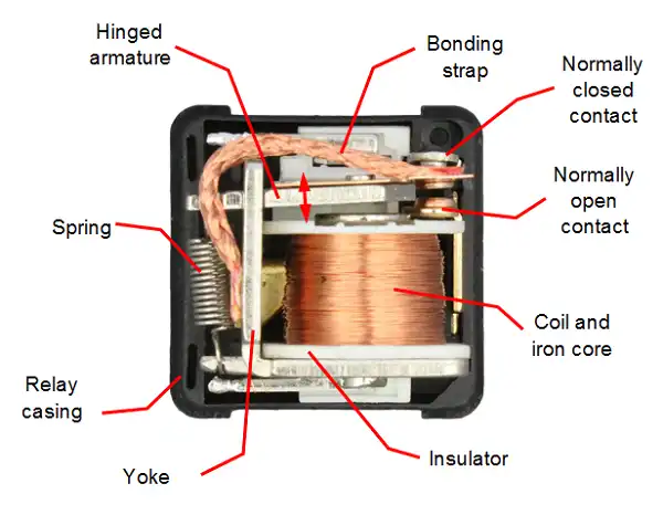
- The important part of a relay is the coil. This coil makes the relay as an electromagnetic switch.
- The principle of electromagetism is applied in relays. When a current passes via the relay coil, an electromagnet is set up. It pulls one switch contact away from another.
Types of Relay Contacts (No, NC & Common)
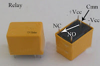
An ordinary relay has two contacts called Normally Open (NO) and Normally Closed (NC) contacts. We can switch the common terminal to NC or NO. The next section deals with the operations of the contacts.
Working Procedure of Relay
Firstly, let’s answer what is a relay driver. It is nothing but a transistor.
- Normally relays are driven by relay drivers.
- This transistor is turned on by some sensors.
- When this transistor (the relay driver) is activated, it feeds current to an electromagnet. The magnet when energized pulls a metal switch to a closed position. And thus ot activates the second high current.
- The relatively small current in the input driver circuit activates the superior current in the output circuit.
[Example] Real Time Application of Relays
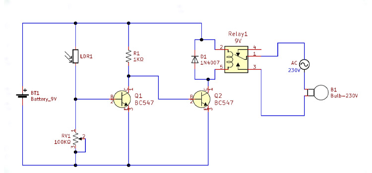
- Suppose you want to build an electronically operated street light system that switches an electrical bulb ON or OFF with respect to the intensity of surrounding light.
- You could use some kind of electronic light sensor circuit (LDR) to sense dark or light conditions, but LDR produces only small resistance variations according to light intensity.
- You could connect the LDR circuit to the input circuit of a relay via relay driver.
- When a small current from sensor flow through this circuit, the relay will activate its output circuit, allowing a much bigger current to flow. Thus turning ON the electrical bulb.
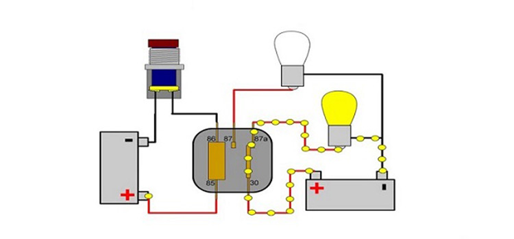
Relay Connection Diagram and Connection Procedure
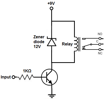
- Identify the two terminals of coil (just open the relay, you can easily find it).
- Connect Vcc to one terminal and fed the other terminal to the collector of driver transistor.
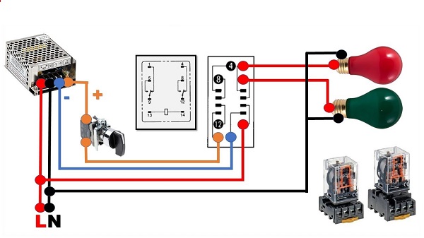
- Then connect the high current neutral line to common terminal of the relay.
- Now connect the NO terminal to any terminals of the load (Bulb, Motor etc.).
- Connect the phase line directly to another terminal of the load.
Conclusion
Innumerable electronic sensors and electrical appliances comprise the field of electrical engineering. But as an electrical engineer or electrical/electronic enthusiast, the goal and challenge are to couple them. Relays serve to bridge that gap and realize the core ideas of projects. Hence, understanding how to connect relay is far more important than it seems.
Subscribe to our newsletter
& plug into
the world of circuits
![Rotary Changeover Switch Wiring Diagram [Explained]](https://www.circuitsgallery.com/wp-content/uploads/2023/10/Rotary-Changeover-Switch-Wiring-Diagram.webp)