555, UM66, BJT Based Water Level Indicator Projects | Simple yet Powerful
You may have seen a wide variety of small electronic projects but if you are finding something unique for your school project or final year engineering project, then this article is just for you. In this article, we will discuss the water level sensors/indicator to detect the water levels inside the water tank or any water reservoir. We also will demonstrate an automatic water level controller circuit that can automatically switch ON and OFF the domestic water pump set depending on the tank water level. The good news is, you can make these projects at your home or college using some common and cheap components. You may only need to spend approximately $5 for a project. The simulations of the circuits are also given below which definitely will help you do your academic project.
First, let’s check what kinds of water level indicator projects you can find below this article:
- An automatic water level controller circuit that can control the water pump without any interruption.
- A digital water level indicator circuit or liquid level sensor that can display the current level of water in any water tank reservoir.
- A ‘Liquid level sensor’ or ‘water level sensor circuit’ that is able to sense the presence and absence of liquid or water in a tank.
- A water tank overflow liquid level sensor alarm circuit that will turn on the alarm whenever the water reaches a certain level.
- The Um66 Based Water Tank Overflow Musical Alarm Circuit which will do the same as the previous project but with a musical alarm.
So, what are you waiting for? Let’s explore these projects below.
Automatic Water Tank Level Controller Motor Driver Circuit | Engineering Project Without Microcontroller
The main advantage of this water level controller circuit is that it automatically controls the water pump without any user interaction. The heart of the pump controller circuit is an NE 555 IC. Here we have manipulated the flip-flop inside the 555 timer IC.This project consists of two water level sensors, one fixed at the top and the other at the bottom. The working of this circuit is almost similar to a Bistable multivibrator.
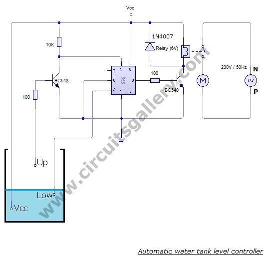
Circuit Diagram of Automatic Water Tank Level Controller Motor Driver Circuit
Components Required for Automatic Water Tank Level Controller Motor Driver Circuit Using 555 timer
- Power supply (6v)
- NE 555 timer IC
- Resistors (100Ωx2, 10kΩ)
- Relay (6V, 30A)
- BC 548 transistor x2
- 1N4007 Diode
Working Procedure of Automatic Water Tank Level Controller
- We know the property of 555 timer IC, i.e. its output goes HIGH when voltage at the second pin(trigger pin) is less than 1/3 Vcc.
- Also we can reset back the IC by applying a LOW voltage at the 4th pin (Reset pin).
- In this project 3 wires are dipped in water tank. Let us define two water levels- Bottom (Low) level and Top (Up) level. One of the wire or probe is from Vcc.
- The probe from bottom level is connected to the trigger (2nd) pin of 555 IC. So the voltage at 2nd pin is Vcc when it is covered by water.
- When water level goes down, the 2nd pin gets disconnected(untouched) from water i.e. voltage at the trigger pin becomes less than Vcc. Then the output of 555 becomes high.
- The output of 555 is fed to a BC548 transistor, it energizes the relay coil and the water pump set is turned ON.
- While the water level rises, the top level probe is covered by water and the transistor becomes ON. Its collector voltage goes to Vce(sat) =0.2.
- The low voltage at the 4th pin resets the IC. So the output of 555 becomes 0V. Hence the motor will turn OFF automatically.
- For simple demonstration of this project you can use a DC motor directly at the output of 555 instead of relay.
- For practical implementation, you must use a relay. Rating of relay is chosen according to the load (Motor). 32 Ampere relay is best suited for domestic applications.
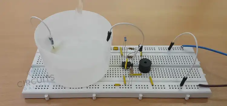
Simulation of the Water Level Controller Motor Driver Project
The mouse click on the bottom level and top-level switches show the level of water. From the animation, you can see that when the water is at the bottom level the motor starts working. And when water reaches the top-level motor stops functioning.
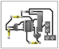
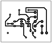
PCB layout of Automatic Water Tank Level Controller Circuit
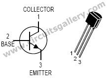
Pin out of the components required for water level controller circuit
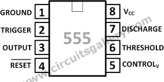
This automatic water tank level controller motor driver circuit is quite easy to implement if you know the basic functioning of 555 timer IC. In fact, 555 has the potential to become the heart of almost any controller project. Ensure the pinouts are studied thoroughly before simulation and practical implementation.
Numeric Water Level Indicator | Liquid Level Sensor Circuit Diagram With 7 Segment Display | Engineering Project
Here we have used a simple real-time encoding circuit with 7 segment display. You can also use it as a water level meter or water level detector.
You can also Combine this project with our other post ‘Automatic water tank level controller’, and you will get a completely automated control system for homes and industries. This water level sensor consists of 8 to 3 encoders (74148- 8 line to 3 line priority encoder) with some water sensor arrangement.
The encoded level can be observed on a 7-segment display with the appropriate driver IC 7447. Let’s see a detailed demonstration of this project below.
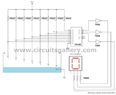
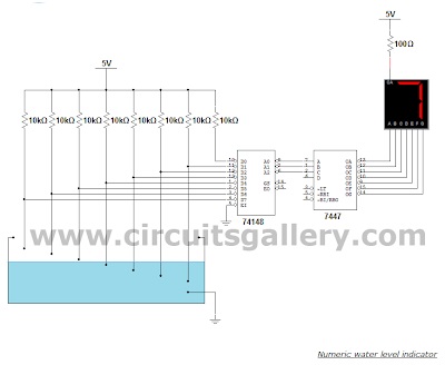
Circuit Diagram of Numeric Water Level Indicator
Components Required for Water Level Indicator
- Power supply
- Resistors (10kΩ x8, 100Ω x3)
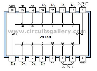
- IC 74148
- IC 7404 NOT gate x3
- Hex display
Working Priciple of Liquid Level Sensor Circuit
- Water level in the tank or any reservoir is sensed using simple pull up resistor arrangement.
- Here we define 7 levels in the reservoir. The sensed values are connected to an encoder circuit.
- The encoder circuit consist of a 74148 IC, which is a 8 line to 3 line encoder.
- A connection from ground is dipped in water reservoier. When water level rises, the ground comes in contact with the particular pin of encoder input.
- Without the ground contact, the encoder input is Vcc through the pull up resistors.
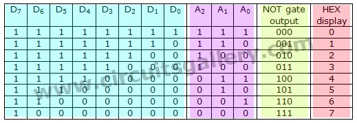
- See the simulation window shown below. Here switch ON indicates water touching the point A.
- While water touches the point A, D1 of encoder IC=0, so the input patern becomes 1111110 which is encoded to 110 binary value.
- The inverted output become 001 using not gate. Thus for each and every level the encoder produces corresponding binary digits.
The HEX Display
- Next section is the ‘HEX Display’ which is a special type of 7 segment display. It is easier to use than the regular seven-segment display because it is already decoded. Each hexadecimal digit is displayed when its 4 bit binary equivalent is received as input, as shown in the truth table below.
- If it is difficulty to get a ‘HEX Display’ you can use ordinary 7 segment display with decoder driver IC 7447. Hence the encoded values are displayed. This circuit will be really helpful for your project.
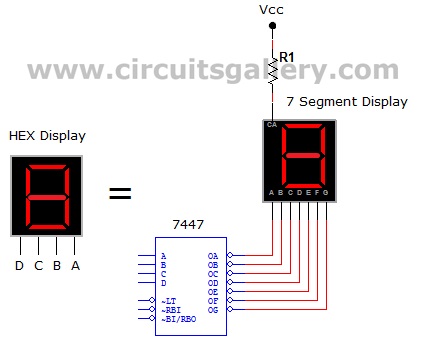
Liquid Level Sensor Circuit Using 7447 Driver IC and 7 Segment Display
You can neglect the 4th input (D) of 7447. Because we are using this circuit to code up to 7 levels. That is up to binary 111. Hence you do not need the 4th input of 7447.
Truth Table of 74148 8-to-3 Line Priority Encoder to HEX Display
Simulation of Numeric Water Level Indicator
Components Pin Outs
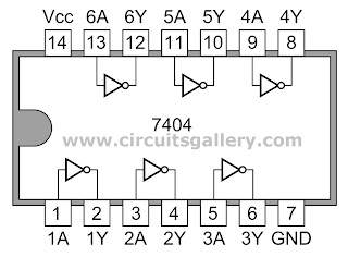
You may have used a set of sensors with comparators to serve the same purpose. But by using the 74148 encoder IC, you can greatly reduce the complexity of the circuit. Again while designing your numeric water level indicator, the use of 7447 Driver IC is also a good alternative. Besides, you need to have a bit of familiarity with the 7404 hex inverters. Hopefully, using them in this project will help you push forwards to future ones.
Water Level Sensor Circuit | Simple Yet Novel Project
You have already learned from above that this circuit can sense the presence and absence of liquid or water in a tank. Furthermore, you may find slightly different approaches to this project without detracting from the main goal of digital water level indicators and automatic water tank level controllers.
Circuit Diagram of Liquid Level Sensor
Components required
- Power supply (or 6V battery)
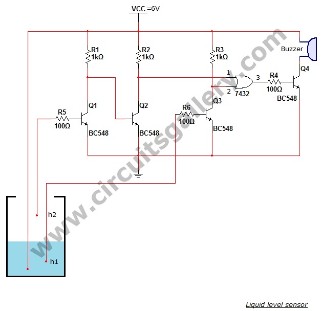
- Resistors (1kΩ x 3; 100Ω x 3)
- Transistors (BC548 x 4)
- IC 7432 Buzzer
Working of the circuit
- The basic principle of this circuit is ‘switching property of NPN transistors’. That is when a transistor is ‘OFF’ its collector voltage is Vcc (6V) and if it is in ‘ON’ state the collector voltage falls to 0.02V (Aprox 0V).
- 0.6V is required to turn on a transistor (BC548). At normal condition Q1= OFF, Q2=ON and Q3=ON thus both input of ‘OR’ gate is Zero..!
- We have dipped 3 wires in the water tank. 1 wire is from power supply and other 2 wires from the base terminals of Q2 and Q3.
- When water level goes below ‘h1’, the wire from transistor Q3 disconnects from the power supply, hence Q3 become ‘OFF’ thus its collector voltage will be Vcc.
- This ‘High’ voltage is applied to the ‘OR gate (IC7432)’ hence its output becomes ‘High’ (if any one of the input of ‘OR’ gate is high, output will be ‘High’) it leads to the turning ‘ON’ of the driver transistor Q4 thus the Buzzer produces ‘Beep’ sound.
- When the water level goes above ‘h2’, Q1 become ‘ON’ because its base terminal is energized by Vcc in the water due to this Q2 will be in ‘OFF’ state. So the collector voltage of Q2 becomes ‘High’.
- This ‘High’ voltage is applied to the ‘OR gate (IC7432)’ hence its output becomes ‘High’ (if any one of the input of ‘OR’ gate is high, output will be ‘High’) it leads to the turning ‘ON’ of the driver transistor Q4 thus the Buzzer produces ‘Beep’ sound.
You can make this electronic project using BC548 transistors and 7432 OR gate IC. The water level sensor circuit alarm will produce a beep sound when the water goes below a specified level (h1) or when water overflows. You can implement thesehome science experiments as science projects for high school students.
Water Tank Overflow Liquid Level Sensor Alarm Circuit
In the previous section, we discussed numeric water level indicators and water level sensor circuits. But those circuits are much more complex and are advanced projects for engineering students. If you are looking for a simple project then you can try this Water tank overflow liquid level sensor alarm circuit.
The main component of this water overflow circuit is the transistor switching part. Here, the circuit simply consists of a liquid (water) level sensor or water level detector with BC547 transistors. Any electronics hobbyist can implement this circuit at his/her home or workplace at a cheap rate ($0.5). The circuit schematic for the water tank overflow alarm is shown below.
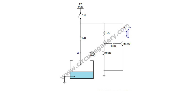
Circuit Diagram of Water Tank Level Alarm
Components Required
- Power supply
- Resistors ¼ Watt (1kΩ x1, 100Ω x2)
- Transistors (BC 547 x 2)
- 6V Buzzer
Working of Overflow Liquid Level Sensor Alarm Circuit
- Water over flow from a tank or reservoir is detected using this simple project circuit. Firstly close the switch SW to turn ON the device.
- Initially the potential at point A in the circuit is Vcc, so the transistor Q1 remains in ON state (Read transistor act as a digital switch) and its collector voltage at Vce sat (0.02V).
- The collector voltage of Q1 is fed to the base terminal of transistor Q2 via100Ω resistor.
- 0.02V is not sufficient to turn ON the transistor Q2, hence it remains in OFF state and the buzzer will not produce any sound.
- A connection from ground is dipped in the water reservoir. When water level rises, the ground comes in contact with the base terminal of transistor Q1. Thus it changes to OFF state and the collector voltage rises to Vcc.
- The high voltage at the collector of Q1 turns ON the transistor Q2 since this high voltage is connected to the base of transistor Q2, then a current flow occur though the buzzer circuit and it produces beep alarm sound. (Read transistor act as a load switch)
- See the simulation window below, here instead of buzzer circuit we have used a LED for simulation. The switch ON is similar to water touching the point A.
It produces a beep sound when the water tank is completely filled with water. The advantage of the water tank overflow liquid level sensor alarm circuit is that it saves water from accidental overflow. So this circuit always prevents the wastage of water in case you forget to switch OFF the motor pump.
UM66 Based Water Tank Overflow Musical Alarm Circuit
If you are finding something like a simple home automation project, then this Water Tank Overflow Musical Alarm Circuit is best for you which is based on the UM66 melody generator IC.
In the previous section, we already discussed another liquid-level sensor alarm circuit that produces a beep sound. But this circuit gives a melody sound whenever the water in the tank overflows. Below is the circuit schematic which produces a melody tone whenever the water tank completely filled with water.
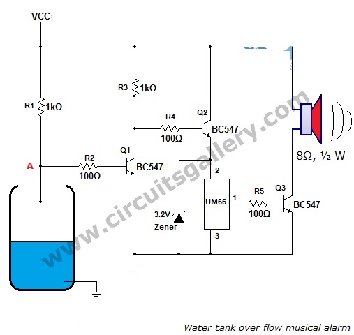
Water Tank Overflow Alarm Circuit Diagram
Components Required for Water Tank Overflow Alarm
- Power supply
- Resistors ¼ Watt (1kΩ x2, 100Ω x3)
- Transistors (BC 547 x 3)
- UM66 IC
- 3.2V Zener diode
- Speaker (8Ω, ½ Watt)
Working Principle of This Simple Home Automation Project
- Initially the transistor Q1 remains in ON state because the potential at the point A in the given circuit diagram is Vcc. So its collector voltage is at Vce sat (0.02V), leading to operate the transistor as a switch.
- The collector voltage of Q1 is fed to the base terminal of transistor Q2 via resistor R4.
- 0.02V is less than the threshold voltage of an NPN transistor, so Q2 is in OFF state and the UM66 musical IC will not get the power to run.
- Vcc gets its connection to UM66 IC through transistor Q2. Wwhenever Q2 is ON UM66 gets the power to operate.
- A probe from ground is curved in water reservoir. When water level rises, the ground comes in contact with the base terminal of transistor Q1 changing it into OFF state so the collector voltage rises to Vcc.
- The high voltage at the collector of Q1 turns ON the transistor Q2. Here, the reason is this high voltage finds its connection to the base of transistor Q2 via the resistor R4.
- Then a current flow occurs from Vcc to UM66 melody generator IC through the transistor Q2.
- 3.2V zener diode is used to regulate the high voltage from Vcc since UM66 is a very sensitive IC and it can’t operate above 3.4V (aprox). You can avoid the use of zener diode if your Vcc supply is 3V, otherwise you must connect a zener diode as a regulator across the UM66 IC as shown in the circuit diagram.
- Upon getting power UM66 produces the melody sound. The current from UM66 IC is not sufficient to drive a speaker hence we are using a BC 547 transistor as amplifier.
- UM66 has an inbuilt tone and a beat generator. The IC is programmed to generate certain frequencies. When power is turned on, the melody generator is reset and melody begins from the first note.
- Many versions of UM66T are available which can generate tone of different songs.
This UM66-based water tank overflow musical alarm circuit basically employs the transistor switching technique. The advantage of this project is that it uses the musical IC. It is capable of producing melody when it detects the presence of water. Finally, it saves water from waste.
Conclusion
Some water level indicators and controller circuits are discussed adobe this article, and we can assure you that you can achieve a great score using any of these on your final year engineering project. The development and working schematics are also demonstrated above. But if you’re still facing problems making these projects, then feel free to ask in our comment section below. Best wishes for your upcoming project.
- Automatic Water Tank Level Controller Motor Driver Circuit | Engineering Project Without Microcontroller
- Numeric Water Level Indicator | Liquid Level Sensor Circuit Diagram With 7 Segment Display | Engineering Project
- Water Level Sensor Circuit | Simple Yet Novel Project
- Water Tank Overflow Liquid Level Sensor Alarm Circuit
- UM66 Based Water Tank Overflow Musical Alarm Circuit
- Conclusion
Subscribe to our newsletter
& plug into
the world of circuits
Esun gran proyecto
Gracias Dr.
You’re very welcome! I’m glad to hear that you appreciate the project. If you have any more questions or need further assistance, please feel free to ask.