Electronic Quiz Buzzer Circuit Diagram using PIC Microcontroller
Usually, high-level quiz competitions are very much time-oriented as it becomes significant to determine who has answered first. So here we’ll see how to make a buzzer system that helps to decide the winners. Actually, I designed this circuit of buzzers for a quiz program conducted in our area and then I thought it may help someone, so I decided to introduce it here.
This game show buzzer circuit uses PIC16F877A and a LED matrix to display who has pressed the button first. As soon as someone hits the button first, all other buttons are disabled helping to find the person or group which are ready to answer the question. A reset button provided for the quiz master enables all the switches again for the next question. The led matrix helps to display the number in a larger size and it’s designed to blink continuously. The buzzer will be ON for a second when anyone presses the button.
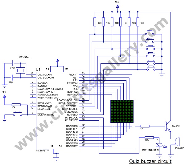
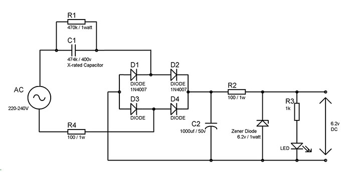
Quiz Buzzer Circuit Diagram
Components Required
- PIC16F877A
- LED matrix 8×8
- Transistor BC548
- Resistor (1K,10Kx7,220)
- Capacitor(33pfx2)
- Crystal (12 MHz)
- LED Green
- Buzzer 5V(PCB Type)
- Push-button x7
Quiz Buzzer Schematic Working
- The LED matrix is connected through PORTB and PORTD of the microcontroller; the cathode row is connected to PORTB and the anode row is connected to PORTD.
- When the power is ON, a green LED starts to glow indicating that all switches are ready to press and the LED matrix is blanked by sending PORTD=11111111 AND PORTB=00000000.
- PIC microchip will continually scan the pins of PORTC to check if someone presses the button. It will check the next button only if the present button is not pressed.
- While programming I had chosen the ‘if’ statement so as to avoid activation of two buttons at the same time by checking each pin from 0 to 7 of PORTC. The probability of this occurring is very low (And I know it’s a little bit unfair if that happens). The use of ‘case’ statements will check all the pins at the same time which may lead to the activation of two buttons at a time.
- The pins of PORTC are connected to +5V (pull up) through a 10K resistor, so if no one pressed the button PORTC gets 11111111 as default.
- Pressing any switch will make a short circuit to the ground getting a logic zero at the corresponding pin of PORTC and so the program execution will enter into the sub-function (loop) of the particular group number to display on the LED matrix.
- Here I interfaced the LED matrix directly to the PIC microcontroller which makes the circuit simpler.
- When the program execution enters into any particular sub-function(loop), it will enable the buzzer by sending a logic 1 to the 5th pin of PORTC and it sends a logic 0 after 1 second (make a beep sound of one second long).
- Then enters into the matrix loop, which scans each column with a delay of 3 milliseconds.
- PORTB sends the data corresponding to the column; a higher scanning speed will make see the display as a number due to the persistence of the vision of the eye.
- Upon pressing the reset button, program execution will return to the main program.
program
•#define LED_A PORTB
#define LED_K PORTD
void L_1();
void L_2();
void L_3();
void L_4();
void L_5();
void L_6();
void clear();
int i;
void main()
{
trisb=0x00;
trisd=0x00;
trisc=0B00111111;
portc.f7=1;
while(1)
{
if (PORTC.F0==0)
{ L_1();
}
else if (PORTC.F1==0)
{ L_2();
}
else if (PORTC.F2==0)
{ L_3();
}
else if (PORTC.F3==0)
{ L_4();
}
else if (PORTC.F4==0)
{ L_5();
}
else if (PORTC.F5==0)
{ L_6();
}
else clear();
}
}
void L_1()
{ portc.f6=1;
delay_ms(1000);
portc.f6=0;
portc.f7=0;
while(1)
{
for(i=0;i<35;i++)
{
DELAY_MS(3) ;
LED_A=0B00100000;
LED_K=0B10111101;
DELAY_MS(3) ;
LED_A=0B00011100;
LED_K=0B00000001;
DELAY_MS(3) ;
LED_A=0B00000010;
LED_K=0B11111101;
DELAY_MS(3);
}
clear();
delay_ms(400);
}
}
void L_2()
{portc.f6=1;
delay_ms(1000);
portc.f6=0;
portc.f7=0;
while(1)
{
for(i=0;i<20;i++)
{
DELAY_MS(3) ;
LED_A=0B01000000;
LED_K=0B10111001;
DELAY_MS(3) ;
LED_A=0B00100000;
LED_K=0B00110001;
DELAY_MS(3) ;
LED_A=0B00010000;
LED_K=0B01100101;
DELAY_MS(3) ;
LED_A=0B00001000;
LED_K=0B01101101;
DELAY_MS(3) ;
LED_A=0B00000100;
LED_K=0B00001001;
DELAY_MS(3) ;
LED_A=0B00000010;
LED_K=0B10011001;
DELAY_MS(3) ;
}
clear();
delay_ms(400);
}
}
void L_3()
{ portc.f6=1;
delay_ms(1000);
portc.f6=0;
portc.f7=0;
while(1)
{
for(i=0;i<20;i++)
{
DELAY_MS(3) ;
LED_A=0B01000000;
LED_K=0B10111011;
DELAY_MS(3) ;
LED_A=0B00100000;
LED_K=0B00111001;
DELAY_MS(3) ;
LED_A=0B00010000;
LED_K=0B01101101;
DELAY_MS(3) ;
LED_A=0B00001000;
LED_K=0B01101101;
DELAY_MS(3) ;
LED_A=0B00000100;
LED_K=0B00000001;
DELAY_MS(3) ;
LED_A=0B00000010;
LED_K=0B10010011;
DELAY_MS(3);
}
clear();
delay_ms(400);
}
}
void L_4()
{ portc.f6=1;
delay_ms(1000);
portc.f6=0;
portc.f7=0;
while(1)
{
for(i=0;i<20;i++)
{
LED_A=0B01000000;
LED_K=0B11100111;
DELAY_MS(3) ;
LED_A=0B00100000;
LED_K=0B11000111;
DELAY_MS(3) ;
LED_A=0B00010000;
LED_K=0B10010111;
DELAY_MS(3) ;
LED_A=0B00001000;
LED_K=0B00110101;
DELAY_MS(3) ;
LED_A=0B00000100;
LED_K=0B00000001;
DELAY_MS(3) ;
LED_A=0B00000010;
LED_K=0B00000001;
DELAY_MS(3) ;
LED_A=0B00000001;
LED_K=0B11110101;
DELAY_MS(3) ;
}
clear();
delay_ms(400);
}
}
void L_5()
{ portc.f6=1;
delay_ms(1000);
portc.f6=0;
portc.f7=0;
while(1)
{
for(i=0;i<20;i++)
{
DELAY_MS(3) ;
LED_A=0B01000000;
LED_K=0B00011011;
DELAY_MS(3) ;
LED_A=0B00100000;
LED_K=0B00011001;
DELAY_MS(3) ;
LED_A=0B00010000;
LED_K=0B01011101;
DELAY_MS(3) ;
LED_A=0B00001000;
LED_K=0B01011101;
DELAY_MS(3) ;
LED_A=0B00000100;
LED_K=0B01000001;
DELAY_MS(3) ;
LED_A=0B00000010;
LED_K=0B01100011;
DELAY_MS(3) ;
}
clear();
delay_ms(400);
}
}
void L_6()
{ portc.f6=1;
delay_ms(1000);
portc.f6=0;
portc.f7=0;
while(1)
{
for(i=0;i<20;i++)
{
DELAY_MS(3) ;
LED_A=0B01000000;
LED_K=0B11000011;
DELAY_MS(3) ;
LED_A=0B00100000;
LED_K=0B10000001;
DELAY_MS(3) ;
LED_A=0B00010000;
LED_K=0B00101101;
DELAY_MS(3) ;
LED_A=0B00001000;
LED_K=0B01101101;
DELAY_MS(3) ;
LED_A=0B00000100;
LED_K=0B01100001;
DELAY_MS(3) ;
LED_A=0B00000010;
LED_K=0B11110011;
DELAY_MS(3) ;
}
clear();
delay_ms(400);
}
}
void clear()
{PORTB=0X00;PORTD=FF;}
Conclusion
Hopefully, you like this quiz buzzer circuit diagram. It is easy to implement and also fun to operate.
Subscribe to our newsletter
& plug into
the world of circuits