Home Security Alarm System Circuit Diagram
Have you ever thought about home security? And implementing your own home security alarm systems? It’s one of the simplest and most interesting circuits for electronic beginners. Our new home security equipment uses an LDR (Light Depended Resistor) to detect security problems. Theft attempts and other security threats can be eliminated by using this simple circuit as the security system.
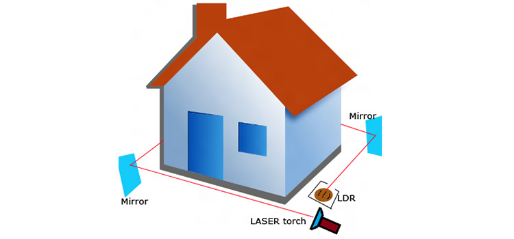
This home security alarm is also best suited for school students for their high school science projects. You have to provide an optical path (with LASER beams) around your home to implement this alarm system for the home. The LASER path is made possible via one LASER torch and 3 mirror arrangements that enclose the whole area. Please refer to the Project Arrangement section below to make this optical (light) path. We have explained the home security system in detail.
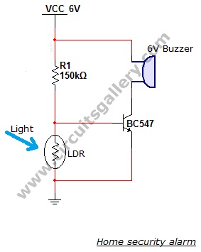
Circuit Diagram of Home Security Alarm
Components Required
- Battery 6V
- Resistors ¼ watt (150kΩ)
- LDR (Light Depended Resistor)
- Transistor BC547
- 6V Buzzer
Working of Home Security Alarm
- This circuit is based on LDR (Light Depended Resistor), a variable resistor in which the resistance varies according to the light intensity falling on it.
- The LDR and resistor R1 forms a potential divider network, which is the main part of our security alarm circuit.
- Here transistor acting as switch.
- The voltage drop across the LDR drive the transistor switch. The transistor is ON when the voltage drop is above cut in voltage (0.6V).
- LDR has low resistance (mΩ range) in the presence of light and high resistance (MΩ range) in the absence of light.
- In our security alarm, a LASER light allows to fall on the LDR continuously using 3 mirrors (see the project arrangement figure).
- Light from other sources should not be allowed to fall on the LDR, so place the LDR in a box with a single hole to pass LASER.
- In this situation, the resistance of the LDR is too low, since the LASER light is continuously allowed to fall on the LDR surface.
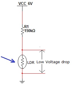
- Thus the voltage drop across the LDR is also low [V=IR (Ohm’s law)], which is insufficient to turn ON the transistor so the transistor remains in OFF state.
- When a person (eg: thief) makes a block to the continuous flow of LASER beam, then the light falling on the LDR gets blocked thus its resistance increases to a high value in the order of MΩ range (According to Ohm’s law V=IR).
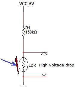
- While resistance increases the voltage drop also increases, when this voltage drop exceeds the cut in voltage of the silicon NPN transistor (0.6V; BC547), it will turn ON.
- Then current from Vcc starts flows to ground via the Buzzer and transistor, which makes the beep sound.
- The beep sound from the security alarm gives the indication of some security failures.
Simulation (Animation) Of the Project
To realize the concept we are providing animation/ simulation of the Home security alarm circuit below. For animated demonstration, we use LED instead of Buzzer.
Project Arrangements
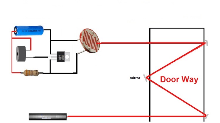
The above image shows the arrangement of the LASER path for the Home security alarm.
Conclusion
This home security project is very simple to implement. It is a perfect choice not only to show at your science fair or for school assignments but also reliable for ensuring the security of your house.
Subscribe to our newsletter
& plug into
the world of circuits


.png)
.png)
Very good project for young students and home elders to secure their ideas.Well done my dear teachers who have constructed this simple project. Please do continue to teach us generally for the same kind of ideas! Thank you. From hobbyist – Karachi- Sind- I.R. Pakistan
Thank you for your comments and stay with us for more informative articles.
Good project and I like it
Thank you for your positive feedback! We’re delighted to hear that you appreciate the project. If you have any questions or need further information, please feel free to ask. Your feedback is valuable to us!