Amplifier Circuits Using Op-amp Inverting, Non-Inverting and MOSFET
You may already know that Amplifier circuits are two-port electronic circuits that receive electric power from a power supply and increase the amplitude of the signal at its output in regular terms. But do you know how to make amplifier circuits using Op-amp and MOSFET or how do they work?
Inverting amplifiers are one of the most popular operational amplifier circuits that try to resist change and avoid saturation at their output signals. It simply helps to stable the extreme gain of an open-loop DC amplifier using some suitable resistors.
The non-inverting amplifiers are also similar to inverting amplifiers, but they provide a gain to the input signal without changing the polarity of the signal and without any phase shift. The input impedance of a non-inverting amplifier is extremely large, typically 100 MΩ.
The Op-amp 742 inverting and non-inverting amplifier circuits with their simulation with output waveform including the working principles are discussed below this article. We also have discussed MOSFET transistor-based power amplifier circuits in this article that can be operated between the +35V to -35V range. So, let’s read by the end of this article carefully to learn about these circuits properly.
Op Amp 741 Inverting Amplifier Circuit | Simulation With Output Waveform and Working Principle
What is the Op-amp 741 inverting amplifier circuit and the simulation with output waveform including the working principle are explained here. So, let’s check them out below.
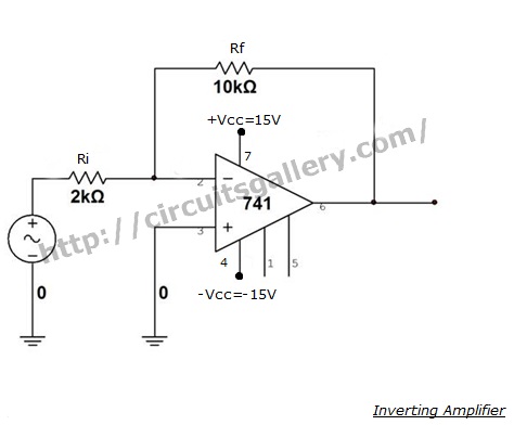
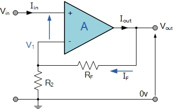
Circuit Diagram of Inverting Amplifier
Components Required
- 741 Op Amp
- Resistors(10kΩ,2kΩ)
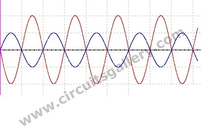
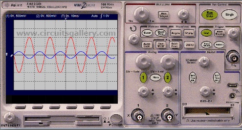
Output waveform
Working of Inverting Amplifier
- The non-inverting input is held at 0v
- The feedback will try to ensure that the inverting input is very close to 0v. This is because the difference between the inputs must be only µV if the output is not saturated. The inverting input is called a virtual ground.
- The resistors form a potential divider with the center at 0v
- Assume that Vin is 0v. Thus Vout must also be 0v
- If Vin rises then the inverting input is greater than non-inverting and so Vout goes rapidly negative until the two inputs are once again equal (or at least only µV’s different)
- Similarly, if Vin goes negative then the inverting input is less than non-inverting input and so Vout rises rapidly to become positive.
- For the amplifier to work properly the output must be able to change very quickly in order to react to the changes in the input. This limits the maximum frequency at which the amplifier can operate.
- The ratio of Vin and Vout depends on the ratio of the resistors in the potential divider and so, at low frequencies, the gain depends only on the values of Rf and Ri.
- At higher frequencies the gain of the op-amp is limited and so sets an upper limit on the gain of the amplifier circuit.
Gain Equation of Op Amp 741 Inverting Amplifier Circuit

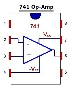
Components Pin out
Simulated Output Using Multisim
Though named amplifier, an op amp 741 inverting amplifier circuit comes in the use of multiple mathematical operations. Most important and prominent among them include integration and diffraction. Besides, it is also used in circuits as simple as filters, and oscillators to as important as voltage and current regulators.
Op Amp 741 Non Inverting Amplifier Circuit With Simulated Waveform
Let’s learn about the Op-amp 741 non-inverting amplifier circuits with simulated waveform below.
Non-Inverting Amplifier Circuit Diagram
Components Required
- 741 Op amp
- Resistors(1kΩ,10kΩ)
Working of Noninverting Amplifier
- The working of non-inverting amplifiers is similar to that of inverting amplifiers except that the output has no phase shift.
- The resistors Ri and Rf form a voltage divider network.
- Negative feedback is provided by applying a little of output voltage to the inverting input terminal through the potential divider network Ri and Rf.
- The voltage gain of the amplifier is determined by the ratios of Rf and Ri since Gain, A=1+Rf/Ri
- So the amplitude of the output voltage signal can be varied by varying either of the resistors Rf or Ri.
Design
Gain of noninverting amplifier, A=1+ Rf/Ri
Let the gain be 11 so that the ratio Rf/Ri=10. Take Ri=1k and Rf=10k
Here we have demonstrated and explain how to build a non inverting amplifier circuit using op-amp 741.
50 Watt Power MOSFET Amplifier Circuit Diagram
Let’s learn about the 50 watt power MOSFET amplifier circuit diagram below.
What is A Differential Amplifier
A difference amplifier is a type of power amp with two differential inputs that amplify the difference between two input signals. Here we are dealing with the circuit diagram and working of high voltage differential amplifier using IRF9530 and IRF530 MOSFET. You need a dual power supply circuit for this amplifier which I had posted earlier.
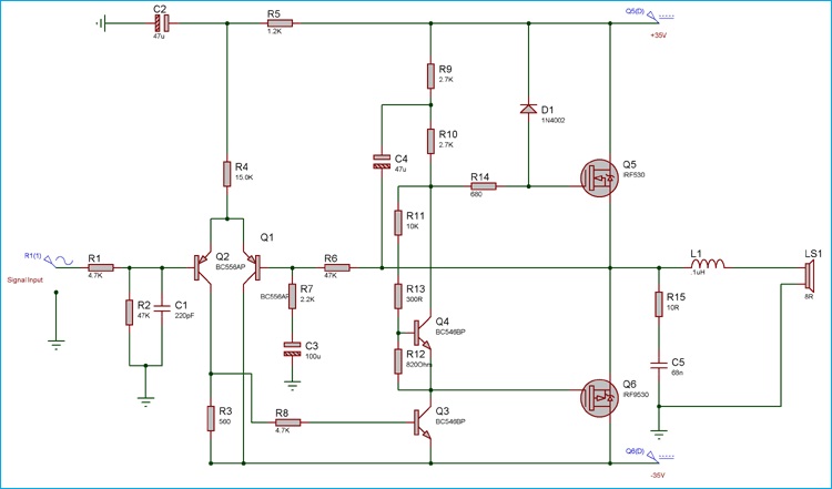
Circuit Diagram of MOSFET Power Amp
Components Required for 50 Watt Power MOSFET Amplifier Circuit
- Dual power supply
- Resistors ¼ watt (10Ω; 560Ω; 680Ω; 820Ω; 1.2kΩ; 2.2kΩ; 2.7Ωk x 2 4.7kΩ x 2; 10kΩ; 15kΩ; 47kΩ x 2)
- Preset (1kΩ)
- Electrolytic capacitors (47µF,16V x 2; 100µF,50V x 4)
- Capacitors (220pF; 68nF)
- Inductor (12 turns of enameled copper wire on a 1cm diameter plastic former- 0.1µH)
- Diode (1N4002)
- BJT transistors (BC556 x 2; BC546 x 2)
- MOSFET (IRF530; IRF 9530)
- Speaker (8Ω)
Working Procedure of 50 Watt Power Amplifier
- Input audio signal is pre filtered using a low pass filter and applied to the differential amplifier based on transistors Q5 and Q6.
- C7 removes the high frequency noise signals and R16 limits the current through C7.
- The intermediate stage consisting of Q3 and Q4 acts as a driver to the next MOSFET stage.
- To adjust the quiescent current, a preset is connected at the base of Q3 transistor.
- The IRF530 and IRF9530 MOSFETs are important part of this amplifier.
- Here the two MOSFETs form a complementary push pull driver amplifier which is the output stage of our power amplifier.
- R14 and C8 reduce the unwanted noise occurring in the MOSFET amplifier.
- The capacitors C5 and C3 are power supply filters. The output speaker is driven via an inductor to make noise free amplifier.
MOSFETs are great components in terms of their efficiency. But they tend to become too hot when in prolonged operation. Hence, while building your 50-watt power MOSFET amplifier circuit don’t forget to provide a suitable heat sink for MOSFETs.
Conclusion
Everything about the amplifier circuit and how to build an inverting and a non-inverting amplifier circuit using the Op-amp 741 is demonstrated in this article. We also have discussed and explained the 50 watt power MOSFET amplifier circuit diagram above and hopefully, now you can make your own amplifier after reading this article. If you have any confusion regarding this topic, don’t hesitate to ask in our comment section below. Thanks for reading.
Subscribe to our newsletter
& plug into
the world of circuits

![What Size Potentiometer for Volume Control [Everything You Need to Know]](https://www.circuitsgallery.com/wp-content/uploads/2023/09/What-Size-Potentiometer-for-Volume-Control.webp)
