Simple LM35 Electronic Temperature Sensor Indicator Circuit
This is a simple temperature sensor circuit diagram using the LM335 temperature sensor and LM3914 IC. Here the complete temperature range becomes observable through an array of LEDs. The LM35 is an integrated circuit temperature sensor for sensing temperature on a degree Celsius scale. The LM3914 is an efficient display driver cum Milli volt measuring IC and it is very easy to apply as an analog meter circuit. In this temperature monitoring system, the millivolt output from the LM35 is converted to a digital temperature indicator by means of LM3914 IC. The LEDs in this circuit show the temperature levels digitally via 20 steps. This temperature indicator circuit is absolutely the simplest to build, as it is based on a single stand-alone IC LM3914 by Texas Instruments, which executes the entire process of indicating the temperature range.
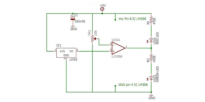
Circuit Diagram of Digital Temperature Sensor
Components Required for Temperature Monitor Circuit
- Power supply (7V or above)
- 1% or 2% film resistors (200Ω; 499Ω x 2; 1kΩ; 1.2kΩ; 1.5kΩ x 2)
- Capacitors 16V or above (1µF; 20µF)
- Potentiometers (1kΩ x 3)
- LM35 temperature sensor
- LM3914 driver IC
- 20 LEDs
Working of Temperature Indicator
- The LM35 series are precision integrated-circuit temperature sensors, whose output voltage is directly proportional to the Celsius (Centigrade) temperature range of operating temperature (−55° to +150°C).
- The LM35 converts the temperature into a millivolt range at its output pin. For each single degree variation in the temperature, the IC LM35 generates an output with a 10 mV variation.
- LM35 is capable of working with single power supplies and plus-minus power supplies. It draws only 60 μA from its supply, it has very low self-heating.
- Here LM3914 display driver IC is used to convert the LM35 output voltage to indicating LEDs.
- The IC LM3914 is basically a milli volt measuring tool which is able to convert a varying millivolt input into an equivalent LED indication providing a linear analog display.
- Current through the LED is regulated and programmable, this aspect allows the operation of the entire system from less than 3V and eliminates the requirement for resistors.
- Refer to the block diagram of LM3914, a high input impedance buffer functions with signals from ground to 12V and is protected against overturn and overvoltage signals. This comparator drives 10 different LEDs with respect to a reference voltage.
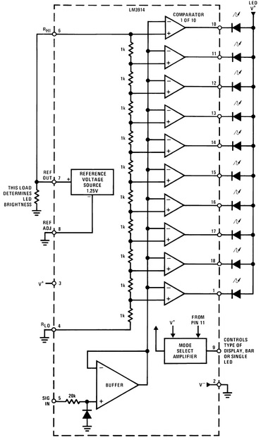
- The reference voltage is given by the resistor potential divider network.
- Here the resistor thread is coupled to the internal 1.25V reference voltage. Thus for each 125mV increase of input signal, a comparator will switch ON further LED.
- LED brightness control is another feature of this IC. The current drawn out of the reference voltage pin (pin 7) decides the LED current.
- Pin 9, the Mode Select input is used to interconnect two LM3914 ICs. Here we have connected two ICs using this mode pin.
- Under rapidly changing signal conditions, the built-in hysteresis avoids the jumping of LEDs immediately from one to another.
- Due to the presence of internally regulated transistors, LM3914 has the ability to work with low or fluctuating voltages. It also permits the display driver to interface with logic circuitry, opto coupled solid-state relays, and low current incandescent lamps.
Conclusion
Here we’ve learned about the construction and working principle of a temperature sensor. It can accurately sense the environment temperature in real-time and can be implemented for any IoT-based projects.
Subscribe to our newsletter
& plug into
the world of circuits
![How to Drive a Ground Rod in Rocky Soil [Step-by-Step Guide]](https://www.circuitsgallery.com/wp-content/uploads/2023/09/How-to-Drive-a-Ground-Rod-in-Rocky-Soil.webp)
![[Answered] Can I Use 12/2 Wire For Lights?](https://www.circuitsgallery.com/wp-content/uploads/2023/12/Can-I-Use-12-2-Wire-For-Lights.webp)
![Does Super Glue Conduct Electricity [Explained]](https://www.circuitsgallery.com/wp-content/uploads/2023/12/Does-Super-Glue-Conduct-Electricity.webp)
