Oscilloscope Input Impedance | Everything You Need to Know
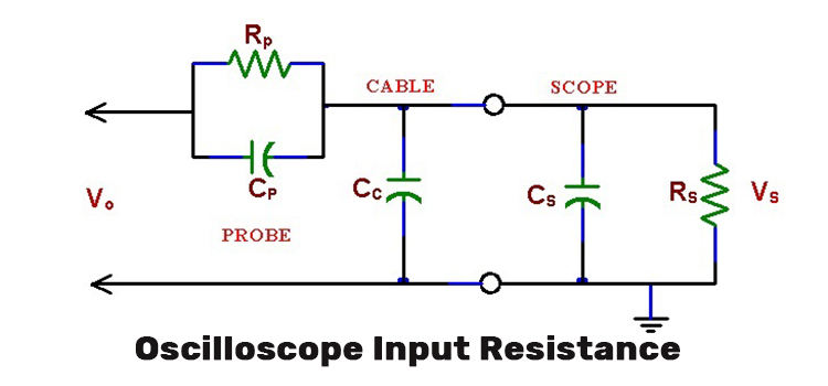
The input impedance of an oscilloscope is often referred to as a complex quantity. It is represented by a resistor connected parallel with a capacitor between the scope input terminal and the ground terminal. So, we can say that the total impedance is dependent on frequency.
An ideal oscilloscope should have an infinite amount of input impedance. This assures the complete avoidance of the unintentional loading of the system. Adding a load to a signal alters the system measurement.
How to Solve Oscilloscope Input Impedance Problem
The input impedance of an oscilloscope remains constant due to having both resistive and capacitive components. Thus it can disrupt the performances of the measured circuits and causes limitations in the high-frequency performances of oscilloscopes.
To solve this problem, we use a scope probe. This is an attenuator that is consisted of two impedances in a series. Once it is connected between the point of measurement in a circuit and the scope input, the other is attached to the ground. The scope probe balances the capacitances and makes the impedance independent from the frequency.
The Reason for Having a High Input Impedance
An oscilloscope has high input impedance so that a negligible amount of current is being drawn from the tested circuit. If otherwise, more current would flow through the probes and oscilloscope, than through the circuit itself.
At lower frequencies, the input impedance of the oscilloscope is kept high to not let the circuit be distorted.
A lower input impedance would appear as a load to the tested circuit. It would affect the signal level as we touch the scope probe for the test point. That’s why a probe head must have a very large input resistance and a very small capacitance.
Can an Oscilloscope Measure Impedance
Yes, an oscilloscope can measure impedance. To measure an impedance Ẑ one should know the complex amplitude Û which is the voltage across the impedance for a given complex amplitude Î of the current through the impedance.
However one is only able to measure voltages by the oscilloscope. This problem can be dealt with since it is possible to measure two voltages concurrently relative to a common ground. The unknown impedance is placed in series with a known auxiliary resistor R (or more generally: a known impedance) as shown in the figure.
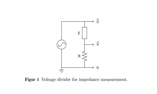
The voltage Û across the combination of the two components as well as the voltage V across the resistor only is measured on channel 1 and channel 2 of the oscilloscope respectively. It is the same current Î that flows through the unknown impedance and the resistor.
Hence, as V=ÎR
Thus, Û = (R + Ẑ) *Î
Assume, A^ is the complex ratio between the voltages we have,
Â=V/ Û = R /(R + Ẑ).
From the equation, we can derive,
Ẑ = {(1/Â) – 1}*R.
When Would You Use a 50-Ohm Oscilloscope
The reason why we use a 50 Ohm oscilloscope is to reduce the reflections from the connected source. Here, we use a 50 Ohm characteristic impedance cable, such as an RG58 or RG174 cable.
In a 50 Ohm cable, the signal will see a 50 Ohm instantaneous impedance as it is generated to the scope. After entering the scope, by keeping the instantaneous impedance is constant, there will be no reflection, and we would see the actual voltage launched into the cable by the source.
Frequently Asked Questions
How do you achieve impedance matching?
Impedance matching is arranging the source and load impedances to minimize signal reflection or maximize power transfer. In DC circuits, the impedances of the source and load should be equal to each other. In AC circuits, the source should either equal the load or the complex conjugate of the load, depending on the goal.
Impedance matching is obtained through two techniques. One is called conjugate matching and the other one is regarded as reflection-less matching.
How do you achieve maximum signal power transfer?
Maximum power transfer is obtained when the output impedance of the source is equal to the complex conjugate of the input impedance of the load (ZS=RL-JXL). This is called conjugate matching. Minimal signal reflection is achieved when the source impedance is equal to the load impedance (ZS=RL+JXL), which is called reflection-less matching.
Conclusion
A probe is chosen whose input resistance and capacitance match with the input resistance and capacitance of the provided scope. As it is desired for the probe to have the least influence on the circuit that is being measured—this is referred to as the loading effect. Resistance and capacitance matching is critical for guaranteeing proper signal transfer and signal accuracy.
Most modern scopes have either 50 Ω or 1 MΩ input resistance. Generally, a 1 MΩ input is commonly used. A 50 Ω input resistance is used for high-speed signals (microwaves), propagation delays in logic circuits, and circuit-board impedance testing.
Subscribe to our newsletter
& plug into
the world of circuits