IoT Based Automated Irrigation System Using ESP8266 NodeMCU
In the previous article, we’d gone through simple soil moisture-based smart irrigation system, and at that time itself, we’d thought of implementing and publishing the same system with IoT, an IoT-based automated irrigation system. IoT is a term that is quite trending these days and so I hope everyone is familiar with that. Having said that, let’s get straight into our project details.
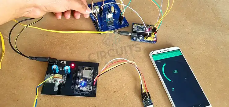
In contrast to the last one, this system will let us monitor our smart farm via the internet, cool huh? Corresponding to the previous one, this IOT based irrigation system will read the moisture content in the soil and switch on the water pump, but with the difference that it will be sending the moisture level and water pump status to the internet allowing us to see it through a webpage on our phone or PC.
How to setup Arduino IDE with ESP8266 Board
1. Download and install the latest Arduino IDE from the Arduino website www.arduino.cc
2. Open Arduino IDE and click File→ Preferences. Paste the URL “http://arduino.esp8266.com/stable/package_esp8266com_index.json” on the Additional Boards Manager URLs field and click OK
3. Open Tools→ Board→ Boards Manager. And then search ESP8266 and click install.
4. Open tools→ Board→ NodeMcu 1.0
5. Connect NodeMcu Board and open Tools→ Port→ COMxx, where xx is the corresponding port number
And so that’s it, now we’re ready to program.
How to Deploy
• Connect NodeMcu ESP8266 to your PC.
• Upload the program
• Open tools→ Serial monitor→ Set baud rate to 9600
• Press the reset button
• Get the IP address displayed on the serial monitor and enter it into the browser of your PC or any other device
which is connected to the same wifi network, for example, http://192.168.xx.xx
Working of IoT Based Automated Irrigation system
Here NodeMcu works as the server it will respond to the requests from the clients, now let’s see the program in detail.
#include <esp8266wifi.h>
#include <wificlient.h>
#include <esp8266webserver.h>
#include <softwareserial.h></softwareserial.h></esp8266webserver.h></wificlient.h></esp8266wifi.h>
Loading the required libraries for ESP8266
int MOTOR_PIN = D3;
bool pump_status=0;
int adc_value;
Declare three variables; where MOTOR_PIN = D3 is the pin to connect the water pump, pump_status is the variable to store water pump status (to check if it’s running or not), and adc_value to store and process the ADC (Analog to Digital Converter) value, which is read from the moisture sensor
const char* ssid = "Your Wifi Name";
const char* password = "Your Wifi Password";
Storing the wifi SSID and Password to connect to the wifi network
ESP8266WebServer server(80);Creates server object and the server starts on port 80, then the client connects to the server through IP and port 80 (192.168.100.xx:80)
void handleRoot() {
String page = "";
page +="";
page +="<meta http-equiv="\"refresh\"" content="\"1\"">";
page +="<title>IOT Moisture Sensor</title>";
page += "";
page +="";
page +="<center>";
page +="<h1>Moisture: "+String(adc_value)+"%</h1>";
page +="<p></p><h1>Pump Status:";
if(pump_status)
{
page +="<font color="\"red\""> ON</font></h1>";
}
else
{
page +="<font color="\"green\""> OFF</font><p></p>";
}
page +="</center>";
page +="";
page +="";
server.send(200, "text/html", page); //Send web page
}This is the function to call when a client request is received, it will return an HTML webpage, the contents of the page will change depending on the adc_value and the pump_status
void setup(void){
Serial.begin(9600); // Initialize serial port with baud rate 9600
pinMode(MOTOR_PIN, OUTPUT);
WiFi.begin(ssid, password);     //Connect to your WiFi router
Serial.println("");    //send a newline
pinMode(A0, INPUT);  //set analog pin A0 as input to connect moisture sensor
// Wait for connection
while (WiFi.status() != WL_CONNECTED) {   // this while  loop wait for wifi connection
delay(500);
Serial.print(".");
}

//If connection successful show IP address in serial monitor
Serial.println("");
Serial.print("Connected to ");
Serial.println(ssid);
Serial.print("IP address: ");
Serial.println(WiFi.localIP());  //IP address assigned to your ESP

server.on("/", handleRoot);      //Which routine to handle at root location

server.begin();                  //Start server
Serial.println("HTTP server started");
}
The setup function does all the initialization steps, most of the lines above are commented to know what they are for
void loop(void)
{
adc_value = analogRead(A0);
adc_value = map(adc_value,500,1023,100,0);
if(adc_value < 5)
{
pump_status = 1;
digitalWrite(MOTOR_PIN, HIGH);
}
else
{
pump_status = 0;
digitalWrite(MOTOR_PIN, LOW);
}
delay(100);
server.handleClient();          //Handle client requests
}
Above is the loop function
adc_value = analogRead(A0);This reads the analog value from the pin “A0” and stores it to the integer variable adc_value, pin A0 is connected to the moisture sensor, if water content in the soil is high, then correspondingly the ADC value is high.
adc_value = map(adc_value,500,1023,100,0);Esp8266 has a 10bit ADC, hence the value can vary from 0 to 1023. We’ll map it into 0 to 100, our moisture sensor value varies from 500 to 1023, and so we map it from 500 to 1023.
if(adc_value < 5)
{
pump_status = 1;
digitalWrite(MOTOR_PIN, HIGH);
}
else
{
pump_status = 0;
digitalWrite(MOTOR_PIN, LOW);
}
Lastly, checks the adc_value, if the value is less than 5, then set pump_status to check the status of the motor, and set the pin that is connected to the water pump, thus switch on the water pump, else switch off the water pump and clear the pump_status variable.
Conclusion
This is how a hefty IoT-based automated irrigation system is built. For engineering students, this is a cool project. We hope to come up with more IOT based projects, so stay tuned.
Subscribe to our newsletter
& plug into
the world of circuits