Object Detecting Android Mobile Phone Controlled Bluetooth Robot Using PIC Microcontroller 16F877A
Today I came up with another engineering project for electronics and communication students. It’s an Android mobile phone controlled Bluetooth robot using a PIC microcontroller with object detecting capability. After installing MikroElectron’s Robot Control App from Play Store you should be able to control the robot with your android phone/ tablet over a Bluetooth signal.
The eye-catching feature of this project is the ‘objects detection’ capability with the help of an Ultrasonic sensor. So you don’t have to worry about the robot hitting any object or wall in front of it. The robot will navigate safely without touching any obstacles. Moreover, it will make beep sounds if any obstacle is found and an LCD screen is used to display the distance to the specified object.
Speaking of the hardware, I’ve used PIC16F877A to control the robot, ultrasonic sensor will generate ultrasonic pulses to detect objects and calculate the distance, an LCD screen to display distance, HC-06 / HC-05 Bluetooth module for communicating to the Robot wirelessly.
Well, let’s see how to make a mobile robot for your academic project.
Components for Android Robot
- PIC16F877A
- L293D IC
- 7805 IC
- LCD 16×2
- Ultrasonic Sensor HC-SR04
- Crystal 20MHz
- Transistor BC548
- Resistor (10Kx2, 1Kx2)
- Capacitor (33pfx2, 10uF/16V)
- PCB
- DC gear motor (100 rpm x 2)
- Robot frame and wheels
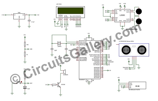
Circuit Diagram of Bluetooth Controlled Robot
Working Principle of Obstacle Avoidance robot
For simplicity let’s consider this project has 2 parts- the Bluetooth navigation section and an object detection section.
Bluetooth Wireless Navigation
- HC-06 / HC-05 Bluetooth module is used to receive data from the android based devices.
- After pairing (connecting) the Bluetooth module with an android phone or tablet, open the application and connect to the paired device HC-06 or HC-05.
- Android application will send letters ‘F’, ‘B’, ‘R’, and ‘L’ to move the robot forward, backward, right, and left respectively.
- These are received by the Bluetooth receiver, those letters are available in the TX pin of HC-06.
- TX pin of Bluetooth module is connected to RX pin (26) of PIC microcontroller, which receives information from the Bluetooth module.
- That information is used as an interrupt to switch between user-defined functions that we have specified.
- We have written different functions to perform assigned tasks viz Move forward, backward, turn left, and right. These functions will change the values of pins RC0, RC1, RC2, and RC3. Wheel rotations are controlled by these pins.
- Here we are using IC L293D to drive the wheel motor, which is capable of driving 2 motors at a time.
Object Detection
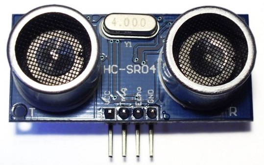
- HC-SR04 ultrasonic sensor is used to measure the distance between object and robot.
- HC-SR04 ultrasonic sensor has 4 pins- Vcc, Ground, TRIGGER, and ECHO.
- ECHO is connected to Pin 23 and TRIGGER to Pin 24 of the PIC Microcontroller respectively.
- Initially, we may trigger the ultrasonic sensor by applying a TRIGGER pulse via Pin 23 of PIC MCU.
- This will initiate the sensor to transmit out 8 cycles of ultrasonic burst at 40 kHz and then it waits for the reflected ultrasonic burst. When the sensor detects ultrasonic from the receiver, it will set the ECHO pin to high (5V) and delay for a period (width) which is in proportion to the distance.
- The time difference between transmitted and reflected ultrasonic burst is calculated using the TIMER1 module of PIC.
Distance Calculation
The distance is calculated by the formula-
distance = speed*time/2
Where,
Speed= Velocity of light.
Time= Time between transmitted and reflected waves.
- The calculated distance is displayed over an LCD display; LCD is driven by PORT B. (Read more about LCD Interfacing with PIC Microcontroller).
- If the distance is less than 25 cm, the robot will rotate right 90 degrees and produces a beep sound to inform us that an object has been found. This will help to avoid objects and acquire a safe path.
- Then you have to code it accordingly.

Conclusion
I have used a 12V /1.2Ah rechargeable battery to operate the robot. If you can use a Li-ion or more advanced battery of quite a close capacity it would be much better. Because it is heavy and loses charge on the go for itself.
Subscribe to our newsletter
& plug into
the world of circuits

