High Current Adjustable Power Supply Circuit Using LM317
Variable power supplies are available in different ranges but they provide a very low current of one or two amperes. They can’t drive high power devices like a motor or high power lamps. So to get through such problems I introduce a high current variable voltage power supply circuit that can drive 10A of load. The current handling capacity can be increased simply by connecting 2N3055 power transistors in parallel.
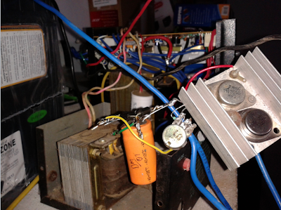
I happened to design a high current adjustable power supply circuit schematic diagram for my inverter battery for safe and quick charging. My 30Ah lead-acid inverter battery takes more time for constant voltage charging when I use an LM317 variable voltage regulator. This is due to its lower output current.
So I connected a power transistor which helps to increase the current without varying the voltage. 2N3055 can handle 15A, so by connecting parallel make add the individual currently. This can be used as a regulated 48V DC power supply or 24 V DC power supply. The maximum input to this DC variable power supply is 37 volts.
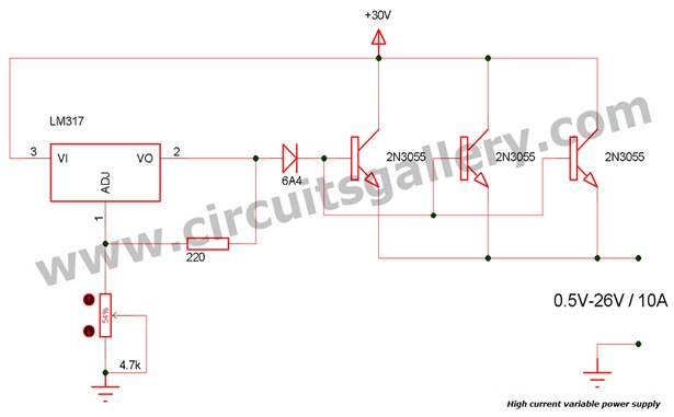
High Current Adjustable Power Supply Circuit Diagram
Components Required for Variable Power Supply
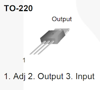
- IC LM317
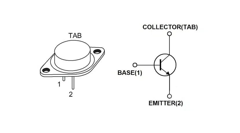
- Transistor 2N3055 X 3
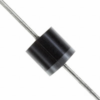
- Diode 6A4
- Resistor (220 ohm, 4.7K(POT))
Working Procedure of High Current Adjustable Power Supply Circuit
- As you know LM317 is a variable voltage regulator IC. Output voltage of this IC can be varied between 1.25V and 37V.! Yes, this is the best choice of variable power supply circuits.
- Output of LM317 variable voltage regulator in connected to the base of 2N3055 power transistor. We have already discussed LM 317 Variable DC Power supply, but it was low current.
- Here the first section of circuit is same as before but in order to boost current we are using 2N3055 transistor.
- 2N3055 power transistor can handle a maximum of 115 watts and the maximum collector current is 15A.
- In this circuit the output from LM317 directed to parallel combination of 2N3055 power transistors which will increase the output current hence the power also.
- Collector of 2N3055 connected to Vcc and Emitter of each transistor are looped together to get output terminal.
- By varying the resistance of potentiometer output voltage of LM317 IC can be varied. Correspondingly the emitter voltage of power transistor 2N3055 is varied.
- Proper heat sink must be provided for the power transistors.
I used these to charge my 30Ah lead-acid inverter battery. This circuit is tested under i-St@r labs.
Pinouts of Components
Conclusion
Ready-made power supplies are available in the market. But the requirement of a custom high current adjustable power supply circuit will always be required if extensive projects are intended. Keep in mind, the capacitors, diodes, and transistors involved must be rated compatible with the high current ratings.
Subscribe to our newsletter
& plug into
the world of circuits

