Digital Home Automation Projects | Security and Smart Control
The world of electronics is meaningless without the use of circuit boards, capacitors, receivers, and all those small parts. A combination of all those elements makes up a bigger device, which we can control using the remote, controllers, or even smartphones.
As technology has developed, so has the world around us. Even our home is filled with advanced digital equipment. Buying them premade is sometimes a lot more costly, which is inconvenient.
Most of our daily appliances, security products, and digital equipment are the same as before, just with a controller circuit that allows a smart device to connect with it and perform the functions from the designated device.
This brings us to our today’s article about Digital home automation projects that you can perform on your already existing appliances. With a little knowledge and safety, you can do the DIY with ease. We have included 5 different circuit schematics for the project that can be used with your home appliances. And the elements can be picked up from your corner store electronics shop anytime.
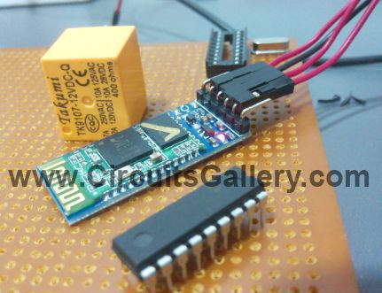
1. Android App Home Automation via Bluetooth Using PIC 16F628A Microcontroller
One of the best discoveries of the century is Bluetooth. You can not only connect your ear-pods and speakers to your smartphone but also use them to control your digital appliances with it. Here we are going to talk about how you can use your Android phone to connect with your home appliances to create automation via Bluetooth using a PIC 16F628A Microcontroller
You only have to do is install an android application on your android phone or tablet, then you can switch ON or OFF any electrical appliances by simply touching the screen of your android phone. The fun part about this automation is you can control up to eight devices, which may include a high-power water pump.
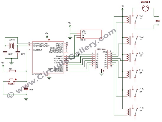
Circuit Schematics of Android Home Automation Project
Components Required for Bluetooth Home Appliances Control System
- Arduino Bluetooth Control App
- PIC16F628A
- Bluetooth Module HC-06 or HC-05
- Relay (12V x6)
- Crystal (20MHz)
- Capacitor (33pf x2; 10µF)
- Resistor (10K)
- IC ULN2003A
- Push Button
Working Principle of Android Home Automation Project
- This smart home system uses an android application and PIC16F628A microcontroller to make the system smaller to accommodate inside a switchboard case.
- To connect the android device with our embedded smart home automation system we use an HC-05 or HC-06 Bluetooth module.
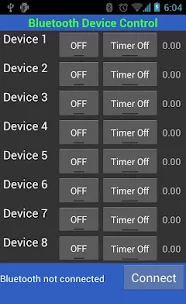
- In the app, you can see eight device buttons. You can edit the names of these buttons as per your requirement like FAN, LIGHT, A/C*, MOTOR*, HEATER*, etc., and configure the App (see section configure Bluetooth App)
- After launching the application you can connect your android tab or mobile device with the Bluetooth module using the default passkey “1234”.
- As the connection is established you can press the buttons, so it will send letters via Bluetooth, it will be available in the TX pin of the Bluetooth module which is connected to the RX pin of the microcontroller.
(* For high-current equipment use high-current handling relays)
Program Execution for Android Home Automation
- In our home, automated system circuitry PIC will continuously check if any serial data is received, which will be stored on a variable ‘A’. Then a ‘switch’ function is to control the output pins at PORT B.
- I have used PORTB to connect devices via relay driver IC ULN2003A. Relays do the switching of devices, which is driven by IC ULN2003A,
- Two pins of PORTB (RB1 and RB2) are used for serial communication and the remaining pins are used to connect devices.
- So totally we used only six pins to control devices, since the app has eight device options you can use PORTA upon requirement.
- For the first device, by pressing a button the App will send the capital letter ‘A’ to the Bluetooth module. It will make PORTB 0th Pin (RB0=1) to HIGH hence turning ON the corresponding relay.
- If you press the button again App will send a small letter ‘a’ to the Bluetooth module. It will make PORTB 0th Pin (RB0=0) to LOW hence turning OFF the corresponding relay.
- For the remaining buttons also it will send B, C, D, E, F, G and b, c, d, e, f, g
- Another advantage of this project is that the App has the provision to switch ON devices for a preset time. With this facility, you can fully automate the system.
- There is a button to switch the ON timer for each device switch, time can be set from one minute to 4 hours.
- The application will automatically send an OFF command to the system by making an alert.
- Appliances are connected to relays, which handle high-current devices, the load that can be handled by the relay is depend on the relay used. If you use a 30A relay you can switch 30A devices.
Configure Android Bluetooth App for Android Home Automation
Now let’s see how you configure Arduino Bluetooth Control App for this project.

There is no pre-configuration required for this App, just edit the name of Switches to Light, Fan, AC so on and so far.
Other Applications of the PIC 16F628A Microcontroller
This modern and interesting project can be used both for showing at any project fair or to implement in own home. Follow the above tutorial to fabricate it which doesn’t take more than an hour.
2. DTMF Cell Phone controlled Home appliances | Engineering automation project
Another great way to control your appliances is using a DTMF cellphone controller. You don’t need any Bluetooth or wifi for this, but your wired headphones. If you are wondering about a DTMF and know more about its functions we have it as DTMF and DTMF decoder circuits using M8870. This will give you an insight into the whole circuitry and the decoder IC altogether.
Here is how you construct the connections and build the circuit for your appliance.
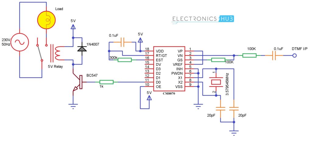
Circuit Diagram of Mobile Controlled Home Appliances
Components Required for Home Automation
- Regulated power supply
- DTMF decoder IC (M-8870)
- Resistors (100Ω; 100kΩ; 70kΩ; 390kΩ)
- Capacitors (0.1µFx 2)
- Crystal oscillator (3.579545MHz)
- IC 7474 D flip flop
- BC547 Transistor
- 6V relay
Working on This Home Automation Electronic Project
- Our project uses an M-8870 DTMF decoder IC which decodes the tone generated by the keypad of a cell phone.
- When you press any key on your mobile phone while a call is in progress, the other person will hear some tones corresponding to the keys pressed. These tones are based on the DTMF (Dual Tone Multi-Frequency) technology.
- Data is transmitted as pairs of tones. The receiver detects the valid frequency pair and gives the appropriate BCD code as the output of the DTMF decoder IC.
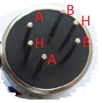
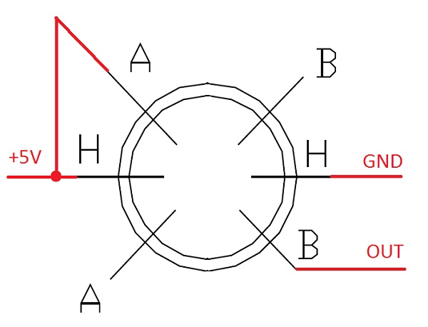
- DTMF signal can be tapped directly from the microphone pin of a cell phone device.
- See the figure below. Cut the microphone wire and you will be able to see 4 wires. Among these wires, you need only 2 wires- Ground and Right as shown in the figure.
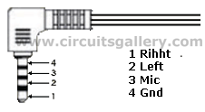
- Select the right wire and connect it as the DTMF input to the decoder circuit. The ground should be connected to the common ground of our circuit.
- The signals from the microphone wire are processed by the DTMF decoder IC which generates the equivalent binary sequence as a parallel output of Q1, Q2, Q3, and Q4.
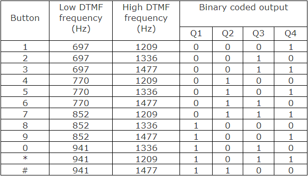
Table Showing Dtmf Low and High-Frequency Tones and Decoded Output
- The output Q4 from the DTMF decoder IC is fed to the clock input of IC 7474 D flip flop which acts as a buffer to the output from the M8870 DTMF decoder IC.
- IC7474 is configured in Toggling mode, that is if it gets a clock pulse the output of this IC (Pin 5) sets to high and further clock pulse resets back the IC. (The outputs toggle whenever a key is pressed).
- When we press and release any of the keys among 1, 3, 5, 7, 9, and *, the DTMF decoder IC generates a high pulse which acts as a clock to our flip flop and sets the output flip flop to high.
- The output of the flip flop is connected to the relay driver circuit via a 100Ω resistor; this output energizes the relay coil through the BC547 transistor and turns ON the bulb that is connected at the normally open terminal of the relay circuit.
Controlling something with just your phone without any connection is hard to achieve. This project can also be put on your school science fair and surely turn some heads. Best of all, it is easy to construct and execute.
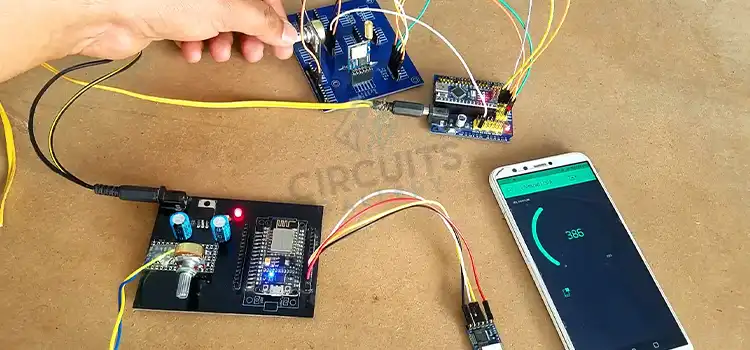
3. SMS-Based Device Control using GSM Modem
One of the neat things about technology is that you don’t need to be present at your home to control your appliances. For instance, you can turn on the air conditioning or the lights before you even come home during the night.
The only thing you will need to do is send a Text to your device and it will activate. And the device that will be present at your home will be a PIC microcontroller that will receive your command. It will relay the command to the PORTD device which will activate your appliance.
Here is how you build it yourself.
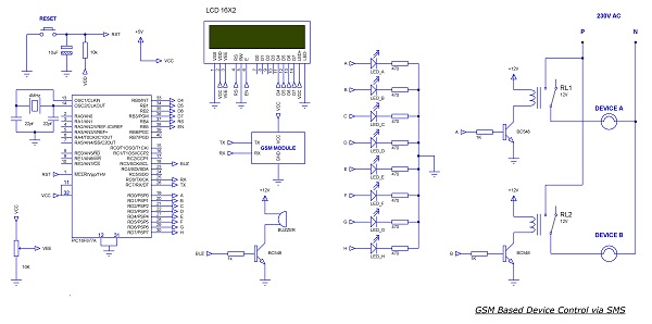
Home Appliances Controlling Using Mobile Phone Circuit
Components Required
- PIC16F877A
- GSM Module
- LCD (2X16)
- Transistor (BC548)
- Resistor (1K, 10K, 470×8, 10K(POT))
- Crystal (4MHz)
- Capacitor (22pfx2, 10uF)
- Push-button
- LED x8
Working principle of the circuit
- The serial pin of the PIC Microchip (RX and TX) is connected to the GSM module to control it via AT commands so as to receive SMS and set the mode.
- When the system is ON, PIC will initialize the GSM module and wait to receive an SMS.
- 2×16 LCD display is connected to the PORTB of PIC, it will display the status of the system (i.e. it will display what the system is doing).
- Initially, the GSM module is switched to Text mode by sending the AT command “AT+CMGF=1”. Here “1” indicates text mode and “0” is used to indicate PDU mode.
- After this setting, PIC will display that it’s waiting for SMS and will wait to receive SMS.
- The reception of SMS is detected by checking the received character; it will send all information about the SMS which starts with”+CMT”. Message text content will start after sending”\n” and end with”\n”. This is the logic I have used here to receive SMS.
- I have used an infinite loop that continuously checks if a ‘+’ is received, followed by ‘C’, ‘M’, and ‘T’.
- Then the system understands that a massage is going to be received and waits for a $ (dollar sign), if done it will store the entire message on a buffer of size 33 named INFO. It’s again split and stored on two separate buffers for further processing.
- After this, PIC will display “SMS IS RECEIVED” in the first row and “DEVICE SWITCHING” in the second row. It also enables a buzzer for 2 seconds as an audio indication of SMS reception.
- A variable “count” is initiated as “1” and the received SMS information is now on the buffer named line1, the letter on line1[0] is skipped and takes line1[1] because the message for ON and OFF is sent as “$ON ABCDEFGH$” and “$OFF ABCDEFGH$”; in both cases Zeroth letter (“O”) is common, so I skipped it.
- The first letter indicates that the message is for ON or OFF. Here I have used two ‘for’ loops, one to set PORTD bits (ON the devices) and another one to reset the PORTD bits(turning OFF the devices).
- ON and OFF detection is done by checking the first character (line1[1]) of the message, “N” for ON and “F” for OFF.
- After detecting the message it will enter into the corresponding loop of SET or RESET pins. Then the relays connected to these pins activate or deactivate.
- For demonstration purposes, I have used LEDs and in the circuit diagram, I have mentioned how to connect a relay in order to connect high-current devices.
- To switch ON the devices, you may send SMS as “$ON ABC$” to ON A, B, and C; “$OFF B$” to switch OFF B.
- We have designed this system to switch 8 individual devices and you can improve it through simple modification of the program and hardware.
SMS-based device control is a cool modern project now a day You can easily make your own using a GSM modem and PIC16F877A.
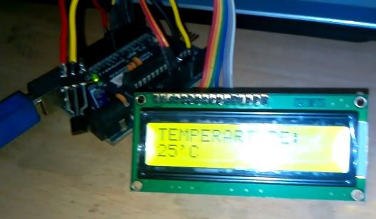
4. Arduino Temperature Sensor or Digital Thermometer with LM35
Sometimes you cannot get the temperature reading on your appliances. Be it an oven, microwave, or heating or cooling air conditioner. For all of that inconvenience, we came up with a combination of an LM35 temperature sensor with an Arduino Microcontroller.
You not only get the temperature reading accurately but also can see it in real-time with an LCD display. It can be used in furnaces, cold stores, and heavy machinery.
To make your life a bit easier, we are going to show you the diagram of the circuit build along with the code needed for the Adruino Microcontroller to work. So let’s dive in.
Components Required for Arduino Thermometer Project
Digital thermometer Arduino uses readily available components that everyone can obtain in any electronics retail shop.
- Arduino
- LM35 Temperature Sensor
- 16×2 LCD Display
- POT 1kΩ
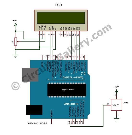
Arduino Temperature Sensor Circuit Schematics
Working Principle of Arduino Temperature Sensor
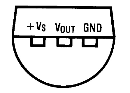
- LM35 is a reasonable temperature sensor available in any of the electronics shops. The output voltage of LM35 is linearly proportional to the Celsius (Centigrade) temperature.
- The output of LM35 is of 10mV/°C scale factor, which means for each 1°C increase in temperature there will be a corresponding increase in 10mV, so we can easily read the temperature value.
- Arduino has an analog pin (A0) capable of reading analog signals from any sensor. As shown in the circuit diagram the analog pin A0 of Arduino is connected to the output pin of LM35.
- Arduino has a 10-bit inbuilt ADC, so it can read values from 0 to 1023, i.e. for zero voltage it reads 0000 and for VCC (5V) it reads 1023.
- Thus I have mapped 0 – 1023 to 0 – 500 because LM35 increments 10mV for each centigrade so the maximum possible increment is 500.
Note: 5V is our supply Vcc, so the maximum increment is 5V
- Using this mapping we can take each increment in the ADC value as a centigrade increment. (If the ADC value is 27, the temperature value is 27°C)
- Now let’s go to the program logic. First, we may have to declare a long variable ‘A’ to store the value read from LM35, which has its range from 0 to 1023.
- Then declare another integer variable, ‘B‘ to store the mapped (converted) value.
- The temperature value is obtained from pin A0 is stored to variable ‘A’.
- Variable A is then mapped or converted to 0 to 500 range and stored on variable ‘B’
- The value of ‘B’ is directly displayed on a 16×2 LCD screen.
Code for Arduino Temperature Sensor
[cc lang=C]
#include long A; int B;
LiquidCrystal lcd(12, 11, 5, 4, 3, 2);
void setup(){
lcd.begin(16,2);
lcd.print(“THERMO METER”);
pinMode(A0,INPUT); }
void loop() {
A=analogRead(A0);
B=map(A,0,1023,0,500);
lcd.setCursor(0,0);
lcd.print(“TEMPERARTURE: “);
lcd.setCursor(0,1);
lcd.print(B);
lcd.print(“‘C “); }
[/cc]
After that, your project will be up and running. You can use this not only at your home but also in your academic project. The advantage of the Arduino temperature sensor is its ease of construction. We had already seen Arduino and its features. Actually, Arduino programming is much easier than you think. You can also build your own alarm clock using an Arduino microcontroller if you want.
5. Home Automation and Security System using Microcontroller ATMEGA8 with Arduino Programming
Home security is our number one priority. As technology develops, there are a lot of devices and gadgets to keep you safe at home. Instead of spending a fortune on security setup, you can build your own automation security and monitoring system with a simple engineering project.
Although it might sound like a bit of a high school project, it does work and the most secure system is based on this method. You will not only get to keep an eye out for intruders but also get to do the following with this automation.
- Sense the temperature level of the room and monitor it using LEDs.
- Controls the temperature using an exhaust fan.
- Automatically open and close the door to make fast temperature control.
- Pump water if necessary, in case a fire is detected.
So let’s dive into the details and process, shall we?
Components Required
- Arduino UNO
- IC 74138
- L293D
- Exhaust fan (12V)
- Vehicle glasswasher pump motor (12V)
- MQ6 GAS sensor
- Thermistor (High resistance type)
- Transistor (BC548x3)
- Buzzer 5V
- LEDs (Greenx3, Yellowx3, Redx2)
- POT (10Kx2)
- Resistor (1Kx3, 10k)
- Relay 12V
- DVD loader tray
- 12v Power supply
- USB cable
Setting up the project
Built around an ATMEGA8 microcontroller, the main advantage of this system is that it uses Arduino programming which makes the easy embedding of the program and at the end of the day it leads to a drastic reduction of cost from about Rs.1500 to around Rs.80.
For demonstration purposes I have used a DVD loader assembly to open and close the door, it has an inbuilt open close sensor which I have used here. Moreover, the MQ6 GAS sensor for detecting the leakage of LPG is an added advantage of this project. When leakage is detected it should run an alarm and switch on the exhaust fan to reduce the density of GAS.
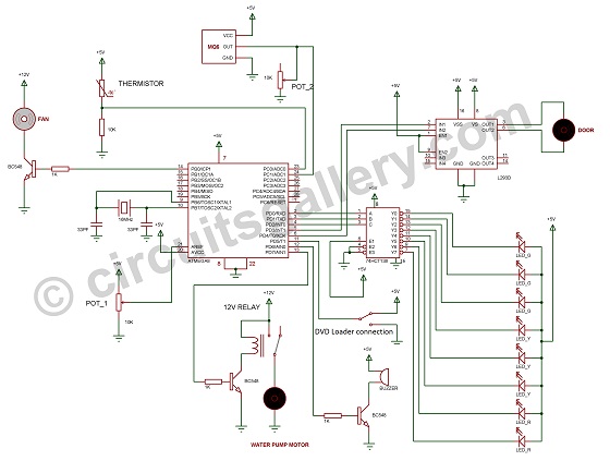
Circuit Diagram
Working principle of home automation and security system
Now let me get into the working of our home automation and security system section by section. The main sensors that I have used here are a thermistor to detect the temperature level and an MQ6 GAS sensor to detect the presence of LPG.
Thermistor Section
- Firstly read the temperature value from the thermistor and monitor on LED with the help of 74328 IC which is a 3 to 8 decoder.
- Two threshold values are used, first, one to enable the open/close of the door and the other one for the fire alarm.
- The temperature level from the thermistor is checked. If the level is less than the first threshold then it does nothing. Else if it’s greater than the first threshold it opens the door with the help of the ‘ON-OFF touch switch’ (Eject button) in the DVD loader assembly, thereby switching on the exhaust fan.
- If the temperature level is greater than the second threshold level (it means there will be a presence of fire) then the controller will switch on the water pump motor to extinguish the fire.
MQ6 GAS Sensor Section
- Then the controller listens to the gas sensor output and compares it with a threshold value, when it’s greater than the threshold, the controller will switch the ON exhaust fan and make a buzzer ON and OFF to make a “beep” sound.
- If the level comes down it switches off the fan and closes the door.
Programming Explanation
- Programming Steps
- Variable declaration
- Pin initialization
- User-defined sub-functions
- Infinite Loop
Variable Declaration
- Declare four variables A, B, C, and D.
- A →Stores the value read from the thermistor via analog pin ADC0.
- B→Stores the mapped values of ‘A’.
- As the Arduino has a 10bit ADC the value can vary from 0 to 1023. To monitor these analog temperature values using 8 LEDs we have to map 0→1023 to 0→8. These mapped values are stored on an integer variable ‘B’.
- C →Store the analog value read from the MQ6GAS sensor through analog pin ADC1.
- D →Stores mapped values of ‘C’.
- Here mapping to 0-100 (Just to get a threshold for the program).
Pin Initialization
Next, initialize the input and output pins which include analog and digital pins. Here we are specifying whether the pin is input or output, pin Mode command is used for it.
User-Defined Sub Functions
Then create separate sub-functions for the open door, close door, buzzer, water pumping, fan ON, and fan OFF.
Infinite Loop
- In the loop function, analog values are read from both the thermistor and GAS sensor and then mapped to corresponding variables.
- Then it checks the temperature value and then sets the corresponding pins as a binary value (pin 0, 1, 2 in Arduino), which is decoded by a 3 to 8 decoder IC 74138. It then drives corresponding LEDs.
- It then checks the GAS sensor mapped value if it’s greater than 50 (threshold) then turns ON the fan and makes the buzzer ON for some time and then the fan is switched OFF.
- Checks the temperature level and if the value is between 3 (first threshold) and 6 (second threshold), then open the door and turn ON the fan.
- If the value becomes less than 3 it switches OFF the fan and closes the door.
- If the door is either fully opened or fully closed then the controller stops the current supply to the door motor, thereby saving current and ensuring the long life of the door motor. It is achieved via special arrangements in the DVD loader.
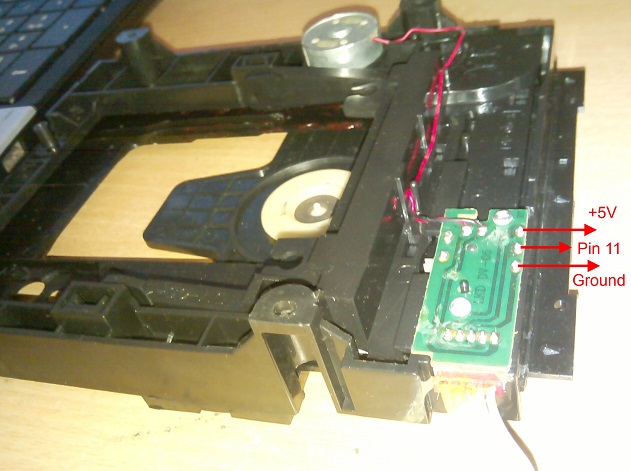
- When the door fully opens, the middle pin of the DVD loader gets connected to +5V. Similarly, when it’s fully closed it gets connected to the ground supply, the middle pin is connected to the controller and it disconnects the motor supply according to the values of this input.
- In case the temperature level exceeds the value 6 (indicates the presence of fire) then it switches ON the water pump and makes a buzzer ON sometimes.
- When the temperature level decreases, turn OFF the water pump.
Conclusion
If you are thinking that it’s just a school hack project, Arduino is excessively used in home automation worldwide. And you can do it on your own in your free time. All of the projects are tasted, performed, and checked thoroughly by our expert engineers on sight. Hence we are confident that they will come in handy for you one way or another. Feel free to impress your science teacher at school if you are thinking about building something on your next science project too.
- 1. Android App Home Automation via Bluetooth Using PIC 16F628A Microcontroller
- 2. DTMF Cell Phone controlled Home appliances | Engineering automation project
- 3. SMS-Based Device Control using GSM Modem
- 4. Arduino Temperature Sensor or Digital Thermometer with LM35
- 5. Home Automation and Security System using Microcontroller ATMEGA8 with Arduino Programming
- Conclusion
Subscribe to our newsletter
& plug into
the world of circuits