GSM Module Projects | PIC and GPS Based
Are you looking for a Final year Electronics Engineering Project? If so, then you’re at the right place where you can find 3 amazing GSM-based electronics and telecommunication engineering projects that you can submit as your academic project.
You may have seen many Electronics Engineering projects that use GSM modems as GSM modems are widely integrated with GSM security systems, and GSM alarms to provide easy user interaction of user to the embedded project.
But in this article, we are going to demonstrate high-class GSM & GPS-based projects. Here is the list of projects that we have discussed below –
- An accident-detecting messaging system using Arduino. You can add this GPS & GSM-based tracking system to any vehicle that will send an SMS if any accident happens with the vehicle.
- A GSM-based notice board using PIC. You can specify what content you want to display on the noticeboard by SMS.
- A GSM module that will let you make calls, send messages, and many other related tasks remotely.
So, what are you waiting for? Let’s read by the end of this article and choose your desired GSM & GPS-based Electronics Engineering Project.
GSM and GPS Based Accident Detecting Messaging System Using Arduino
Do you know what an accident-detecting messaging system is? This GPS module will connect to the vehicle tracking system. It will send an SMS to a predefined phone number about the accident with the geographical location where the accident occurred.
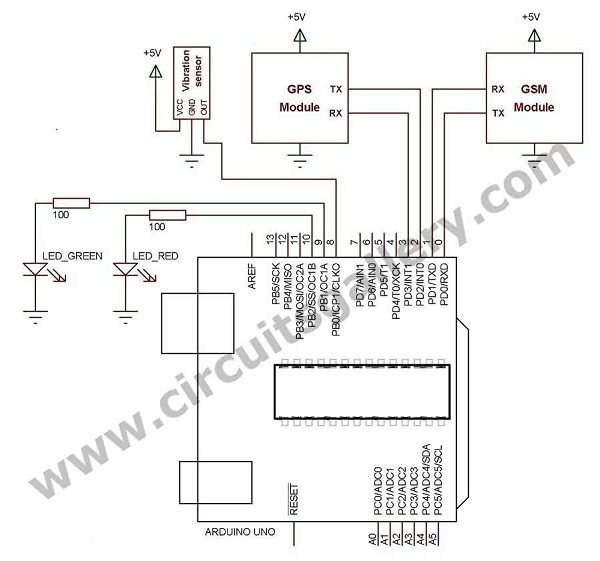
We will use Arduino with GSM, a GPS module, and a vibration sensor for accident detection. It will make a signal when a vibration occurs. The GPS module will continually send the location information, and the GSM module will send SMS. Both modules use serial communication.
Arduino UNO has only one hardware serial port, but as both modules are using serial communication, we will need two hardware serial ports for this. Hence, we are using a software serial library. Now, let’s see how we can make it.
Circuit Diagram of Vehicle Tracking System Using GPS
Components Required for Vehicle Tracking Device
Working Principle of GPS Tracking System
- When vibration occurs the vibration sensor connected with auto tracking device will send a signal to Arduino’s 8th pin
- Arduino will read the GPS data and filter the location information from the received data
- The vehicle tracker will send an SMS command with the text including latitude and longitude to the GSM module
Steps to Implement Vehicle Tracking System Using GPS
- Make connections as a circuit diagram
- Download the TinyGPS library from here
- Add TinyGPS library to Arduino
- Download or copy Arduino code
- Edit the PHONE_NUMBER with your number and upload
- Place a GPS antenna on the outdoor area to get a good satellite signal
- Waite to blink the GPS signal LED
- Waite to glow the green LED connected with Arduino which indicates GPS ready
- Make vibration on the sensor you can see the red LED glows, which indicates SMS is sending
- Make sure that your GSM is ready by simply making a call to the GSM modem or listen the network led is blinking slowly
Arduino Code
#include <softwareserial.h>
#include <tinygps.h>
#define SENSOR 8
#define LED_GREEN 9
#define LED_RED 10
char PHONE_NUMBER[] = "+9199887766XX"; // Enter your phone number here
long lat, lon;
TinyGPS gps;
SoftwareSerial read_gps(4, 3);
void setup()
{
pinMode(LED_RED, OUTPUT);
pinMode(LED_GREEN, OUTPUT);
pinMode(SENSOR, INPUT);
Serial.begin(9600);
read_gps.begin(9600);
}
void loop()
{
bool newData = false;
for (unsigned long start = millis(); millis() - start < 1000;)
{
while (read_gps.available())
{
if (gps.encode(read_gps.read()))
{
digitalWrite(LED_GREEN, HIGH);
gps.get_position(&lat, &lon);
Serial.print("LAT=");
Serial.print(lat);
Serial.print(" LON=");
Serial.println(lon);
}
else
{
digitalWrite(LED_GREEN,LOW);
}
if(digitalRead(SENSOR))
{
digitalWrite(LED_RED,HIGH);
SEND_SMS();
digitalWrite(LED_RED,LOW);
}
}
}
}
void SEND_SMS()
{
Serial.print("AT");
delay(1000);
Serial.print("AT+CMGF=1");
delay(1000);
Serial.print("CMGS=\"PHONE_NUMBER\"\r\n");
delay(2000);
Serial.print("ACCIDENT DETECTED\r\n");
Serial.print("REG.NO:XX.YY.4545\r\n");
Serial.print("LATITUDE:");
Serial.print(lat);
Serial.print("\r\n");
Serial.print("LONGITUDE:");
Serial.print(lon);
Serial.print("\r\n");
delay(2000);
Serial.write(0x1A);
Serial.print("\r\n");
delay(1000);
Serial.write(0x1A);
Serial.print("\r\n");
delay(1000);
Serial.write(0x1A);
Serial.print("\r\n");
delay(1000);
Serial.print("AT\r\n");
delay(1000);
}
</tinygps.h>
</softwareserial.h>The Arduino program can be implemented as a tracking system for vehicles in the real world. You can select this vehicle tracking system project as your academic project. Especially, as an ECE, EEE, or ETE project, it would be quite a good one.
GSM Based Notice Board Using PIC16F877A Microcontroller | Digital Wireless Notice Board
Get your final year project score maximum with our Intelligent GSM Notice board using PIC16F877A. It is capable of displaying SMS received by it. You can specify what content you would like to display on the noticeboard by SMS.
The received message will display on the LCD which will update automatically when the next SMS is received. It also has an audio indicator to inform that SMS is received.

Now let’s begin the technical steps to be carried out for building this GSM Notice board using PIC16F877A.
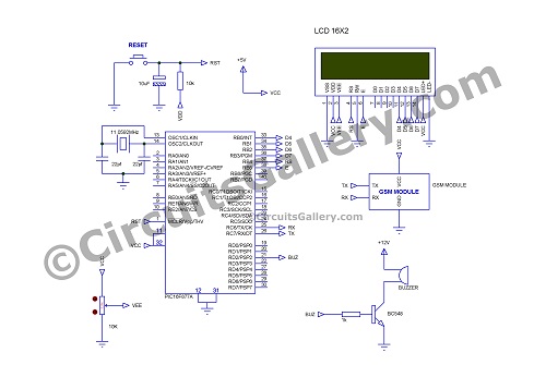
GSM Based Notice Board Using PIC16F877A Circuit Diagram
The following figure shows the GSM notice board using a PIC.
Components Required for GSM Based Notice Board Using PIC16F877A
- PIC16F877A
- Transistor BC548
- Resistor (1KΩ, 10KΩ)
- POT (10K)
- Capacitor (33pfx2, 10µF)
- Crystal (11.0592MHz)
- LCD 16×2
- GSM Modem
- Push button
- Buzzer
Working Procedure of GSM Notice Board Using PIC16F877A Microcontroller
- GSM Modem is used to receive SMS, which is controlled by PIC.
- When the system is ON then PIC will initialize GSM, by sending commands to make the modem in text mode.
- Same time it controls the display which is connected to PORTB in 4-bit mode.
- LCD display shows “GSM is initializing“, after initialization, it shows “Waiting for SMS“.
- When a message is received GSM module starts with this kind of format CMT:[Mob No]:[time]: [Message].
After CMT Detection
- After detecting CMT it waits to receive ‘$’, I used the ‘$’ sign to indicate starting of the message that is to be displayed on the notice board, because the GSM modem sends more data which includes received message time, sender number, etc. like CMT:[Mob No]:[Time]:[Message].
- For our simplicity, I used ‘$’ to enclose the message so our message will be [$ Message content $]. PIC will filter them between two ‘$’ signs.
- The default infinite loop will break only when the ‘$’ sign is received. After receiving ‘$’ it stores the content of the message on the array named as INFO.
- To display the received message content on the LCD, it has to store on two separate arrays for two lines of LCD named as line1 and line2 variables.
- The ending of the message content is indicated by another ‘$’ sign, when storing message content on the array INFO will continually check whether the received character is ‘$’ or not; to break the ‘for loop’ if ‘$’ is received.
After Putting $ Sign
- Here I used 16×2 LCD which has two rows and 16 columns, the arrays line1 and line2 are used to display the content on two rows.
- The message content is first stored on INFO, later it will be spat into two variables (Line1 and Line2).
- Line1 and line2 are 16bit long, those are message content stored by using ‘for loop’.
- Once storing of line 1 and line 2 has been done LCD shows “SMS RECEIVED” on the first row and “UPDATING” on the second row.
- Then it sets the 2nd bit of PORTD to make an audio alert, a buzzer is connected through transistor BC548. It will wait for 2 seconds, and it resets the 2nd bit of PORTD, thus buzzer will turn OFF.
- After line 1 and line 2 are displayed on the LCD, it waits for the next message.
- The content in the LCD module updates on receiving the next SMS.
You may also use Proteus to simulate the GSM-based notice board using PIC16F877A. This would give you more confidence while working with real circuitry. In addition to that, keep your focus more on Tx and Rx terminals.
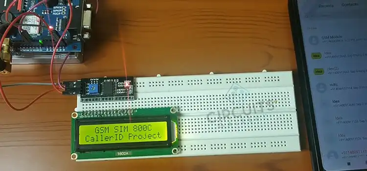
How to Interface GSM Module SIM300 with PIC 16F628A Microcontroller for sending SMS and making Calls
You may be familiar with a GSM module. It lets you make calls, send messages, process messages, and calls, interrupt SMS and CALL, and inform system status, values, GPS location, alerts, etc. within the embedded module.
We have used the PIC16f628A, which has only 18 pins but also has an inbuilt UART module. This circuit can be used as a GSM modem tester also. Let’s check the detailed explanation of interfacing the GSM Module with PIC below.
Components Required for Interfacing SIM300 with PIC 16F628A
- PIC16F628A
- GSM modem SIM300
- IC 7805
- LED x3 (Green, Red, Yellow)
- Resistor (100Ωx3, 10KΩx3)
- Capacitor (0.1µF, 33pfx2)
- Crystal 20MHz
- Push-button
- Dot PCB
- Connecting wires
- 12V DC supply
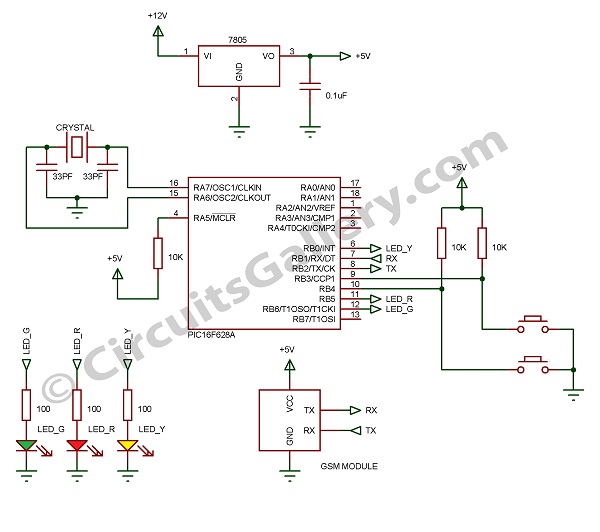
GSM Module SIM300 Interfacing Circuit
SIM300 GSM Module
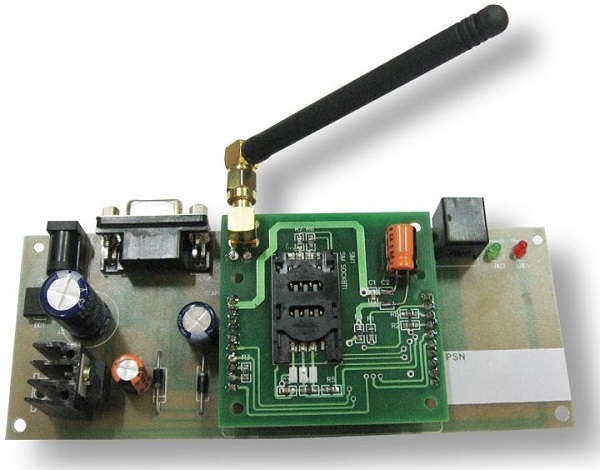
Let’s have a brief look at the embedded wireless module SIM300,
- SIM300 GSM Modem is able to take any GSM network operator SIM card and behave just like a mobile phone with its own unique phone number.
- The RS232 interface lets the modem communicate with the RS232 port of the PC or compatible embedded system circuitry.
- Implementation of SMS-controlled devices, Autoreply; remote control is possible via SIM300.
- The modem can be directly interfaced with the microcontroller. It can be used to send, receive and process SMS/ call
- GPRS facility brings internet and FTP connection to your embedded project.
Popular Applications of SIM300 GSM Module
- SMS-based Remote Control Systems
- Security Applications and Sensor Monitoring
- GPRS/ TFTP Mode Remote Data Logging
Features of SIM300 GSM Module
- Reliable for 24×7 operations
- Status of Modem Indicated by LED
- Easy to Use and Cheap Cost
- Quad Band Modem supports all GSM operator SIM cards
Operation of SIM300 GSM Module
- There are three pins namely GND, RX, and TX can be seen in the SIM300 GSM modem.
- Where GND is a reference and RX and TX are the pins to receive and transmit serial data for a bit rate of 9600.
- To control the GSM modem we send AT commands serially to the GSM modem, you can use the terminal (Putty) to test GSM modem is working or not.
Testing GSM Modem SIM300 with PC
- Power the GSM modem, and the power LED will be ON. Then, the network LED keeps the ON state until the status LED is turned ON and blinks at a faster rate. (Searching for the network if you didn’t insert the SIM card)
- Once it catches the network, the status LED blinking rate reduces accordingly.
- Power on the GSM modem with SIM card and connect to the PC via RS232 serial interface, here I am using a USB to serial converter because my laptop has to serial port..L.
- Open putty and enter AT commands and press enter,
SIM300 AT commands
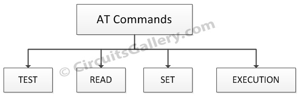
At Commands Send SMS
Set format to Text: AT+CMGF=1
Receiver number: AT+CMGS=9495XXXXXX
Then type message
Cntrl+z
At Commands for Call= Atd9495xxxxxx
AT commands to disconnect call= ATH
Interfacing GSM Module with PIC16F28A
- We have used two push buttons one to send messages and another to make calls; also there are three LEDs GREEN, YELLOW, and RED.
GREEN=System ready to make calls and SMS
YELLOW= Call
RED= Message
- We have defined two user-defined programs send_sms(); and call(); under these programs, we specified AT commands for sending SMS and call respectively.
- After the green LED is ON, press the call button to make calls, this will direct the program to a user-defined program call(); then you can see calling to a number that you pre-programmed.
- By pressing the message button, the program will call a user-defined function send_sms(); you will receive a text message to the number that you programmed.
- I used MicroC to compile the program.
To test a GSM module/modem we have to connect it to a PC and send AT command and then check the response. But it is not possible when we buy this from a shop, This circuit makes you test the GSM Module by simply pressing buttons to make a call and send an SMS.
Conclusion
If you want to get a distinction on your final-year project for electronics engineering, you must need to provide them with an exclusive and intelligent project. We have explained 3 amazing projects that will surely help you get the maximum score on your project. If you are looking for something simple, then go for the GSM Notice board that we’ve discussed in the second segment of this article. If you want to make a complex project then go for the GSM module that we have discussed in the last section. And if you are looking for something extraordinary, then just try the first one which is the GSM and GPS-based accident-detecting messaging system using Arduino. For any assistance regarding these projects, feel free to contact us in the comment section below. Best wishes for your upcoming project.
Subscribe to our newsletter
& plug into
the world of circuits

