Remote Control System Projects
Although infrared was invented in 1980, remote-control gadgets have been around since 1956. And it was a mesmerizing sight for any of us during our youth. Even now, we sometimes feel the urge to control every appliance and device with a remote.
And in today’s era of development and technology, you can create your own Remote Control System Projects with just a few components.
For all of you circuit and gadget enthusiasts, we came up with two project types today.

Remote Controlled Lamp Circuit | IR Remote Night Light
Controlling lamps from distance has been in the back of our minds ever since childhood. But once you enter the world of electronics, nothing like this is unreal or unfeasible. Hence we came up with the remote-controlled lamp circuit with quite basic components.
Circuit Diagram of Wireless Remote Controlled Lamp Circuit
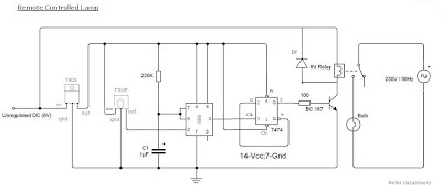
Components Required for IR Remote Controlled Lamp Circuit
- 230v to 6-0-6v step down transformer
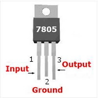
- 7805 voltage regulator
- TSOP IR receiver
- IC 555
- IC 7474
- BC 548
- Diode 1N4007x5
- Resistors (220KΩ, 100Ω)
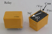
- Relay (6V)
- Capacitor (1μF,470μF)
Working Principle of Remote Controlled Night Lamp Circuit
- Power supply circuit is not shown here. 1st you build a rectifier circuit for 6v DC and proceed
- Maximum voltage of TSOP and 7474 is 5v. So we are using 7805 voltage regulator IC. Its output is 5V
- The output of TSOP is always 5V, and the output will be zero when IR rays strikes on it
- 555 biased as a Monostable multivibrator. Normally its output is 0V, provided that voltage at the 2nd pin must be greater than 1/3Vcc
- When the voltage at the 2nd pin goes below 1/3Vcc output switches to high (5V) for the time T=1.1RC after the time interval output returns to 0V
- 7474 is a D-flip flop. It is wired as Toggle mode. i.e Q’ to D input. 555 used as clock generator
- When it get a clock pulse Output goes to High and remain in that state till next pulse
- On receiving next pulse output goes to low and remain in that state till next pulse
- This process will continue. Output of 7474 is fed to base terminal of BC 548
- BC 548 is driver transistor, when it base voltage is high current will flow through the load
- Here relay is the load and it will energize only when the basevoltage is high and connects the 230v AC supply to the Bulb
- Diode Df is freewheeling diode used to dissipate the stored energy in the inductor load
Datasheets
Components Pinout
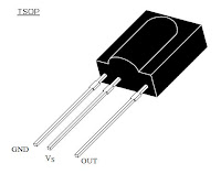

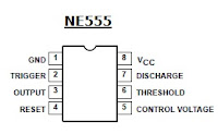
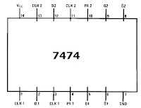
NE555 and 7474 are the two ICs used in this project. So take great care regarding its pinouts and terminals since most silly mistakes in electronics occur there. And remote-controlled lamp circuit is never an exception.
Multi Channel Remote Control System
If you like to control multiple appliances with one remote then we have the circuit system that allows you to control 8 different appliances. The main sections of this multi-channel remote control circuit are the RF receiver and transmitter. By using this circuit we can control 8 devices, each of them independently by pressing the pushbuttons.
When the button is pushed, the corresponding relay is turned ON and is turned OFF on the next push. Here the relay load current is dependent on the relay used. A serial encoder IC HT12E and a serial decoder IC HT12D are used, where the encoder IC encodes the parallel data to serial and the decoder IC decodes the serial data to parallel during the wireless transmission.
You must need a regulated power supply of 5 volts for this circuit because ICs 7476 and 74138 require 5v for their operation. The main advantage of this system is that it does not require a ‘line of sight’ as compared to IR remote control systems; also it gives longer distance control.
Circuit Diagram of RF Remote Control or RF Transmitter- Receiver
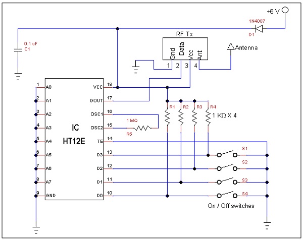
Components Multi Channel Remote Control System
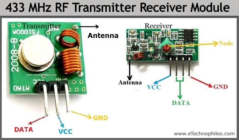
- RF Transmitter Module 433Mhz
- RF Receiver Module 433Mhz
- IC HT12E
- IC HT12D
- IC 7476 4Nos
- IC 74138
- Push-button 8Nos
- Relay 12V,10A 8Nos
- IC 74174
- Transistor BC548
- Resistor (750K,33K,1k 8Nos)
Working Principle of Multi-Channel Remote Control System
- The maximum voltage of TTL ICs is 5v. So we are using a 7805 voltage regulator IC which provides 5V output.
- 74147 is the priority encoder IC which generates the BCD corresponding to the pressed switch.
- It is given to the serial encoder IC HT12E which converts the parallel BCD value to corresponding serial data to transmit through the RF transmitter.
- The RF Transmitter transmits the serial data and the RF receiver receives the serial data, both operate on 434Mhz.
- It is given to the serial decoder IC HT12D which converts the serial data to parallel.
- It is again decoded by a 3 to 8 decoder IC 74138 to operate the relay.
- The output of 74138 is the clock of JK flip flop IC 7476 which operates in toggling mode. (i.e. if one clock is received it inverts the output, thus it turns OFF the relays).
Components Pinout
here we have briefly discussed the Multi-Channel Remote Control, which is a very useful part of any project. You can follow the above step-by-step instruction and fabricate your own.
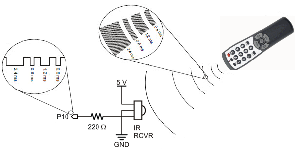
IR Transmitter and Receiver Circuit for Best Remote Control System
A remote control system for appliances makes our life smarter and easier. The wireless remote control circuit may be based on IR waves or RF waves, IR being cheaper. An IR emitter circuit is based on TSOP at the receiver section. Each TSOP operates at a particular frequency which depends on a number present on it. So each TSOP requires a specific remote controller for its operation. There comes the importance of IR universal remote control which can be used to operate all normal hobby circuits.
Here the basic principle of operation is Frequency Shift Keying (FSK). It enables the generation of variable frequency so that it can detect different TSOPs.We are using two 555 timers here, both operating in an astable mode which then drives the IR led. We shall discuss another transmitter circuit with a microcontroller later in another article, which due to the presence of crystal can generate the exact frequency.
How it works
Firstly a 38 kHz IR transmitter circuit is used for which you had to design an astable to generate that frequency. For this, a potentiometer is used, but it was not working properly. It worked only when the potentiometer was being varied. So FSK is implemented to vary the frequency continuously.
Remote Control Transmitter Schematic
Components Required
- NE555 IC X2
- Transistor BC107; BC557
- Resistors (100KΩx2; 10KΩ; 470Ω; 100Ω; 1KΩx2; 330Ω 2.2KΩ)
- Capacitors (0.01uFx3; 2.2uF; 1uF)
- IR Led
- IN4148
- 9V battery
- TSOP
- LED
Working of Infrared Remote Control
Transmitter
- One astable output is at lower frequency and other one at a higher frequency.
- Lower frequency multivibrator controls the frequency of the other.
- From the basic working principle of astable multivibrator, resistors R3, R4 and capacitor C4 determines the frequency, so the frequency can be changed by varying R3. This can be done simply by connecting a NPN transistor (BC 107) in parallel with R3 with a series resistance R5 to limit the current.
- Output of 555 is connected to the base of transistor through a current limiting resistor R7. When the output of first astable is high, the transistor BC107 becomes ON which in turn makes R5 parallel to R3. Then the total effective resistance goes below the resistance of lower resistor value, which reduces the time of astable 555. Thus increase frequency.
- Just the opposite process takes place when the first 555 output is low (OFF).
- Output of the second 555 is connected to an IR Led through a current limiting resistor R6. Led glows in accordance the output frequency which is then detected by the TSOP.
IR Sensor Circuit
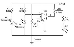
- Here is a simple infrared detector circuit which gives a LED indication.
- TSOP gives active low output. So we are using a PNP transistor.
- When IR rays fall on the TSOP, then by the switching action of the transistor LED glows. You can remove the LED and resistor and connect any appliance you want with the help of relay.
Conclusion
In this IoT era, everyone loves to control their home appliances while sitting on the couch. These projects will be very helpful to build a home automation system in your own house. And it is always fun to control things with just a remote without moving. Which can also aid those who are differently abled.
Subscribe to our newsletter
& plug into
the world of circuits


![How Far Can You Run 12 Gauge Wire on a 20 Amp Circuit [Technically Explained]](https://www.circuitsgallery.com/wp-content/uploads/2023/07/How-Far-Can-You-Run-12-Gauge-Wire-on-a-20-Amp-Circuit.webp)