Common Modulation Transmitters | Circuits and Simulation Matlab Codes| AM, FM, ASK, PSK, OOK
If you are looking for easy and smart electronic projects, we suggest you go for the transmitter projects. You can find many projects with transmitters circuits but in this article, we’ve discussed 8 unique and easy-to-make projects of common modulation transmitters circuits such as AM, FM, ASK, PSK, OOK, etc. and we’ve also used Matlab codes that make them smarter.
Below you can find the following transmitter circuits with simulation –
- A simple 555 timer AM transmitter circuit that is suitable for school projects or science fair projects.
- The simplest and single-transistor FM wireless transmitter circuit which also can be used for school projects or science fair projects.
- Binary Amplitude Shift Keying (BASK) or On-Off Keying (OOK) circuit with diagram – which are one of the best digital modulation techniques.
- A highly-integrated FM audio signal transmitter circuit using a Hi-fi audio chip named VMR6512.
- One of the basic types of digital modulation techniques – Amplitude Shift Keying (ASK) using the Matlab function.
- The Frequency Modulation (FM) in MATLAB.
- A detailed discussion on binary phase-shift keying (BPSK) and applications of PSK modulation with Matlab codes.
- The plotting of AM signals using MATLAB.
All the basics of transmitters with Matlab are discussed below and all these above projects are demonstrated with proper simulations. Let’s check them one by one below.
1. Simple 555 Timer AM Transmitter Circuit Schematic for Science Fair Project
Do you know what Amplitude Modulation (AM) in the transmitter is? AM is a modulation technique where the amplitude of the carrier varies according to the input message signal. AM has been a widely used modulation technique such as walkie-talkie applications due to its longer range but has the disadvantage of lesser noise immunity.
In this project, the 555 multivibrator generates a frequency of AM range, so you can receive the transmitted audio signal in the AM radio receiver. Let’s explore this simple school project below.
Circuit Diagram of Amplitude Modulation Transmitter
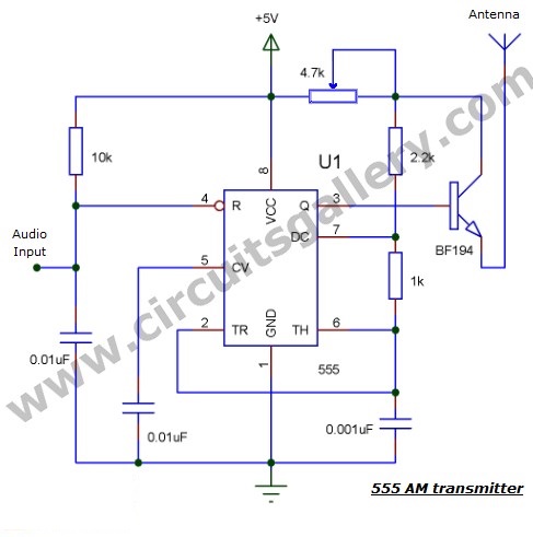
Components Required for 555 Timer AM Transmitter Circuit
- 555 IC
- Transistor BF 194
- Resistor (10K, 1K, 2.2K)
- Pot 4.7K
- Capacitor (.001uF,.01 X2)
- Antenna
Simple 555 Timer AM Transmitter Circuit Working Principle
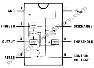
- For a better understanding of the working, please read our article on the 555 astable multivibrator which I had explained in detail.
- Here the carrier signal for AM modulation is generated by a 555 timer operating in astable multivibrator mode with the oscillation frequency set to AM range.
- Input i.e. the message signal is applied to the reset terminal (4th pin of multivibrator).
- If the amplitude of the input message signal is increased, 555 starts to turn ON as it’s connected to the 4th pin. (Since 4th terminal connected to VCC causes it to turn ON because it is an active low logic pin).
- And if the amplitude is decreased, it starts to turn OFF. (As the 4th terminal connect to ground or 0V causes the 555 to turn OFF.)
- The output (3rd pin) is connected to the base of a BF194 transistor as it can operate at high frequencies.
- The emitter terminal of the transistor is connected to an antenna for better transmission. You can use a simple conducting wire as the antenna.
- BF 194 can drive high frequency, here astable multivibrator generates a radio frequency of AM range, then you can receive the transmitted signal in the radio receiver.
Simple 555 Timer AM Transmitter Circuit Simulation Using Proteus
Here is the screenshot of the simulation in Proteus.
Components Pin Out
A simple 555-timer AM transmitter circuit is important in terms of communication engineering using simple electronics. This is often an alternative to FM transmitters, but it has its own limitations.
2. Most Simple FM Transmitter Circuit Diagram | With Design & Troubleshooting
Here is described a single transistor FM wireless transmitter circuit diagram with design. In the telecommunication field, frequency modulation (FM) transmits information by changing the frequency of a carrier wave according to the message signal. We all know that the FM uses VHF radio frequencies, usually 87.5 – 108.0 MHz, to transmit and receive FM signals.
Here you’ll find explanations about FM transmitters including how to make an FM transmitter and how a simple FM transmitter is designed and assembled.
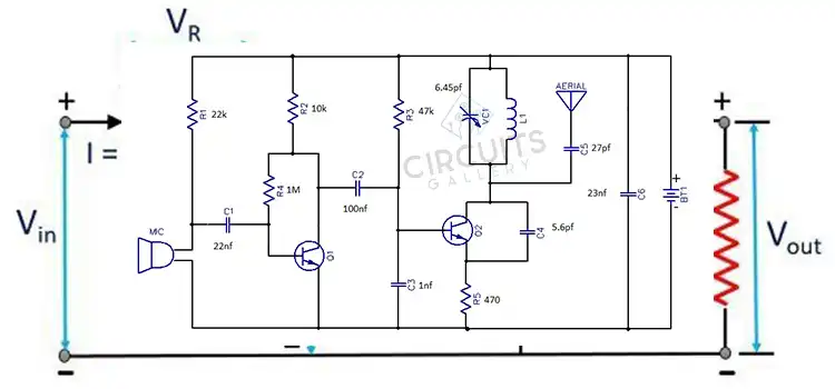
Most Simple FM Transmitter Circuit Diagram
Components Required for Most Simple FM Transmitter Circuit Diagram
- Power supply (9V)
- Resistors ¼ watt (4.7k Ω; 470Ω)
- Capacitors (0.001µF; 4.7µF; 0.022µF)
- Trimmer capacitor (10-100pF)
- Inductor (0.1µH) (6-7 turns using 26 guage copper wire)
- Transistor (2N3904)
- Condenser Mic
- Antenna (Copper wire 20 cm long and 24 gauge)
Working Principle of Most Simple FM Transmitter Circuit
- A condenser microphone is used to accept the sound signals. Inside the mic, a capacitive sensor diaphragm is present. It vibrates according to the air pressure changes and generates AC signals.
- The inductor L1 and variable capacitor (trimmer) form an oscillating tank circuit along with the transistor 2N3904. It is the common NPN transistor used for general-purpose amplifications.
- As long as the current exists across the inductor coil L1 and the variable capacitor, the tank circuit will oscillate at the resonant carrier frequency for FM modulation. Capacitor C2 acts as negative feedback to the oscillating tank circuit.
- Every FM transmitter circuit requires an oscillator part to generate the radio Frequency (RF) carrier waves. The name ‘Tank’ circuit is derived from the capacity of the LC circuit to store energy for oscillations.
- The input audio signal from the mic is fed to the base of the transistor which modulates the LC tank circuit carrier frequency in FM format.
- The variable capacitor is used to change the resonant frequency for fine adjustment to the FM frequency band.
- The modulated signal from the antenna is radiated as radio waves at the FM frequency band. The antenna is nothing but a simple copper wire 20 cm long and 24 gauge.
- The length of the antenna is very significant in the FM transmitter circuit. Here you can use a 25-27 inches long copper wire as an antenna.
Design Your Own Inductor Coil for the Simple FM Transmitter Circuit
Our aim is to resonate the inductor at 88-108MHz band FM frequency. The length, inner diameter, number of turns, etc. are the important factors to be considered while inductor designing. You can design an inductor using the following formula,
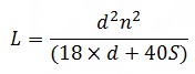
L – Inductance of the coil in µH
d – Coil diameter in Inches
S – Coil length in Inches and
n – Number of turns
[Solved] FM Transmitter is not working | Troubleshooting of FM transmitter circuit
- Firstly, use a battery-operated FM pocket radio to receive the radio signal transmitted via the FM transmitter circuit.
- Secondly, place the FM radio half a meter away from the transmitter and tune it to 80- 108MHz range.
- Then, produce a sound near to the mic, if the tank circuit is properly tuned the sound will be heard in the radio receiver.
- Adjust the shaft of the trimmer and check again whether the sound is clear than the previous case.
- If the sound clarity is fine, stick the inductor coil with glue to avoid further frequency variations.
- Finally, now your best FM transmitter is ready to use.
As a matter of fact, the performance and working principle of a wireless audio transmitter circuit mainly depend on inductor coil specification. Moreover, the value of the variable capacitor is another core contributing factor.
Unquestionably, even a slight change of inductance or capacitor can shift the harmonic frequency from the VHF (88-108 MHz) band.
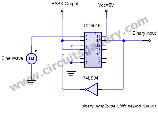
3. BASK or OOK Circuit Using CD4016 | Practical Shift Keying or On-Off Keying Circuit
We are already familiar with Binary Amplitude Shift Keying (BASK) or On-Off Keying (OOK), one of the best digital modulation techniques. In this method, we are going to discuss the amplitude of the carrier that is switched according to the binary data. In this project, binary 1 is represented by a short pulse of light, and binary 0 by the absence of light.
Circuit Diagram of BASK or OOK Circuit Using CD4016
Components Required for ASK Using CD4016
- CD4016 IC
- NOT gate 7404
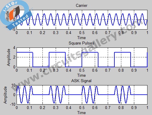
Output Waveform of BASK or OOK Circuit
Working on ASK circuit
- Sine waves can be obtained from a function generator or using an RC phase shift oscillator.
- Two switches inside the quad analog switch CD 4016 are used in the circuit. When the enable input of one gate is high, then the input will appear at the output.
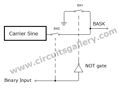
- When the binary data is 1, a sine wave is switched to output because the sine wave is connected to the 1st switch and the binary data is applied to enable the pin (13th pin) of the 1st switch.
- When binary data is 0, the 1st switch is disabled and 2nd switch is enabled using the not gate arrangement.
- The input of the 2nd pin is ground, hence we get 0V for binary 0.
- The output pins of both first and second switches are shorted and the output is taken from it. The block diagram is self-explanatory.
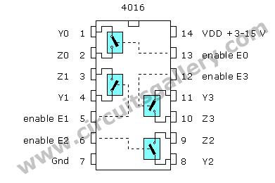
Components Pin out
Amplitude Shift Keying modulation and demodulation processes are relatively inexpensive and easy to implement. BASK or OOK circuit using CD4016 can be used to transmit digital data over optical fiber, point-to-point military communications applications, and more.
4. Simple FM Transmitter Circuit Using VMR6512 | HI-FI Audio FM Transmitter Module | Long Range, Short Range
There are many devices and systems such as cars, digital FM transmitters, Hi-fi wireless headphones, Conference Broadcasting Systems, Accessories of audiovisual entertainment equipment, and Radio stations that need FM radio transmitter.
You can easily make this FM radio transmitter using the VMR6512. This is a wireless audio transmitter chip that integrates a superior digital signal processor (DSP), matching network, frequency synthesizer, RF power amplifier. It can grasp FM audio modulation without any external components.
However, if you want to transmit your voice directly as FM, then you’ll need a pre-amplifier section with this circuit. Now, let’s learn how to make this digital FM transmitter below.
Circuit diagram of FM Transmitter Circuit Using VMR6512
Components Required
- VMR6512 Hi-Fi Audio FM transmitter module
- Push button switch x 3
- Antenna
- Audio amplifier
Constructional Details of An FM Transmitter Circuit Using VMR6512
- Firstly, Construct your audio amplifier.
- Then you can directly connect the output of the Audio amplifier to the VMR6512 Hi-Fi Audio FM transmitter input (Audio in)
PCB layout of FM transmitter
Features of VMR6512 Hi-Fi Audio FM transmitter
- Broadcasts sound without any external components.
- Audio frequency processed by DSP, providing high-quality sound.
- We are using synthetic frequency technology, high oscillation frequency stability, and output power adjustments.
- The frequency range is 88.0MHz to 108.0MHz. The low-end enables extension up to 76.0MHz upon request.
- It can input analog audio or digital audio. VMR6512 possesses external UART interface. You can easily control it with an external CPU or PC machine.
- The IC provides frequency setting UP / DOWN input. So you can and can use it independently.
Pin descriptions of VMR6512 IC
- RST Reset the module with high PWL
- RXD control serial input RX
- TXD control serial output TX
- DIN digital audio data input
- DFS digital audio frame synchronized signal input
- DCLK digital audio clock signal input
- RIN analog audio input on the right
- LIN Analog audio input on the left
- GND Ground
- RFOUT RF output
- GND Ground
- NC No connection
- NC No connection
- DOWN Frequency reduction input, each low PWL impulse output frequency decreases 0.1MHz, continuous low PWL repeats every 0.3 seconds.
- UP Frequency increasing input, each low PWL impulse output frequency increases 0.1MHz, continuous low frequency every 0.5 seconds.
- D/A# Audio input digit / analog selection
- NC No connection
- VCC Power input, 2.7-3 .3 V
Functions of the Pins as per the Manufactures
Reset
Reset pin set to high PWL will reset the controller, DSP, and frequency synthesizer. After reset, the communication frequency will be 100.0MHz and the power will be 115dBuV. The system begins working at 160ms once the Reset signal becomes lower.
Analog audio input Rin, Lin
Rin and Lin is the analog audio input pin of the VMR6512 module. There is a capacitor in the pin. So the other exterior components are less in terms of requirement. Audio input impedance is approximately 56 kΩ.
Digital audio input interface
The digital audio input interface consists of SCLK, DIN, and FS. You can set it to I2S, DSP and Left Justified three different formats through commanding and connected without a glitch with almost all the DSP.
UP / DOWN pin
UP and DOWN pins modify the operating frequency exclusively of the external controller. Each low PWL impulse larger than 0.05 seconds of UP / DOWN pin will make output RF power raise or decrease 0.1MHz. If you stay low PWL, then the operating frequency will change continuously every 0.3 seconds.
RF output
As the unit has internal matching networks, the RF output signal pin should come in direct connection to the line without any components. We propose that the antenna should use a 1/4 wavelength wire or rod antenna.
Pinout of VMR6512 Hi-Fi Audio FM transmitter module
You can build a high-fidelity FM transmitter circuit using VMR6512 for both short and long-ranges. It’s the power of the IC VMR6512 that catches and processes FM signals effortlessly to produce such a magnificent result.
5. Amplitude Shift Keying (Ask) Modulation Code in Matlab
Amplitude Shift Keying is one of the basic types of digital modulation techniques. In ASK, the amplitude level of the carrier signal is switched according to the binary information, while keeping the phase and frequency fixed. Here you’ll learn the ASK simulation using a simple Matlab function.
Matlab Program for ASK
clear all;
clc;
close all;
F1=input(‘Enter the frequency of carrier=’);
F2=input(‘Enter the frequency of pulse=’);
A=3;%Amplitude
t=0:0.001:1;
x=A.*sin(2*pi*F1*t);%Carrier Sine wave
u=A/2.*square(2*pi*F2*t)+(A/2);%Square wave message
v=x.*u;
subplot(3,1,1);
plot(t,x);
xlabel(‘Time’);
ylabel(‘Amplitude’);
title(‘Carrier’);
grid on;
subplot(3,1,2);
plot(t,u);
xlabel(‘Time’);
ylabel(‘Amplitude’);
title(‘Square Pulses’);
grid on;subplot(3,1,3);
plot(t,v);
xlabel(‘Time’);
ylabel(‘Amplitude’);
title(‘ASK Signal’);
grid on;
Generated Ask Signal
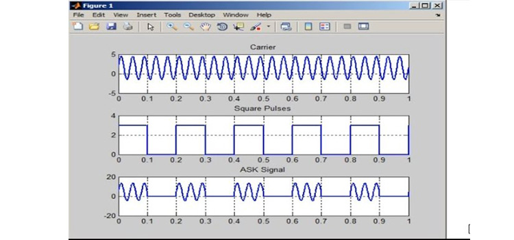
Here the full Matlab code of ASK modulation is provided. You can use this code in any recent version of MatLab for generating an ASK modulation signal.
6. Matlab Code for Frequency Modulation (FM) With Modulation Index
Do you know how to generate frequency modulation (FM) in MATLAB? Before that, you must know what FM (frequency modulation) is.
In FM, the frequency of the carrier signal having a high frequency is varied in accordance with the instantaneous amplitude of the modulating signal having a low frequency. Frequency-modulated signals are widely used in television and radio transmission systems. FM signals can be easily plotted using simple MATLAB functions.
The MATLAB code is shown below, the use of particular code is also given as commented form ( %Comment field ).
You can provide two input frequencies and a modulation index in this given Matlab program. Let’s learn more details about this transmission system below.
Matlab Code for Frequency Modulation
clc;
clear all;
fm=input(‘Message Frequency=’);
fc=input(‘Carrier Frequency=’);
mi=input(‘Modulation Index=’);
t=0:0.0001:0.1;
m=sin(2*pi*fm*t);
subplot(3,1,1);
plot(t,m);
xlabel(‘Time’);
ylabel(‘Amplitude’);
title(‘Message Signal’);
grid on;
c=sin(2*pi*fc*t);
subplot(3,1,2);
plot(t,c);
xlabel(‘Time’);
ylabel(‘Amplitude’);
title(‘Carrier Signal’);
grid on;
y=sin(2*pi*fc*t+(mi.*sin(2*pi*fm*t)));%Frequency changing w.r.t
Message
subplot(3,1,3);
plot(t,y);
xlabel(‘Time’);
ylabel(‘Amplitude’);
title(‘FM Signal’);
grid on;
Hope the above-mentioned Matlab program was helpful to you. To find out more codes, check to ASK, PWM, AM, etc.
7. PSK Modulation Code in MATLAB | Phase Shift Keying
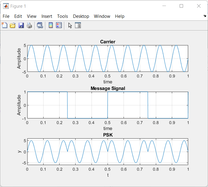
You may be already familiar with Binary Phase shift keying (BPSK). It is one of the basic modulation schemes in which the phase of the carrier signal is varied or switched according to the input message pulses.
When the modulation input is at logic 1, a finite number of cycles of a sinusoidal signal are transmitted and when the input is at logic 0, the phase of the sinusoidal is changed. We have already discussed in detail binary phase-shift keying and applications of PSK modulation above. Now, let’s learn about this Matlab program for BPSK modulation below.
Matlab Program for PSK / Matlab Code for PSK
clear all;
clc;
close all;
A=5;
t=0:.001:1;
f1=input("Carrier Sine wave frequency =");
f2=input("Message frequency =");
x=A.*sin(2*pi*f1*t);%Carrier Sine
subplot(3,1,1);
plot(t,x);
xlabel("time");
ylabel("Amplitude");
title("Carrier");
grid on;
u=square(2*pi*f2*t);%Message signal
subplot(3,1,2);
plot(t,u);
xlabel("time");
ylabel("Amplitude");
title("Message Signal");
grid on;
v=x.*u;%Sine wave multiplied with square wave
subplot(3,1,3);
plot(t,v);
axis([0 1 -6 6]);
xlabel("t");
ylabel("y");
title("PSK");
grid on;
Generated PSK Signal
Carrier Sine wave frequency =10
Message frequency =2
In addition to the PSK modulation code in MATLAB, we have also come up with MATLAB programs for other modulation processes like FSK.
8. MATLAB Code for AM with Modulation Index
We all know that the AM is a method of transmitting signals, such as sound or digital information, in which the amplitude of the carrier wave is changed according to the message signal. It is widely used in the electronic communication field. But do you know how to generate Amplitude modulation (AM) using MATLAB?
If not then don’t worry, because the plotting of AM signals using MATLAB is very easy. Here we are simply adding the carrier amplitude with the message signal to obtain an AM signal. Then the instantaneous amplitude of the carrier gets altered with respect to the modulating signal. Thus, the carrier amplitude varies according to the baseband signal (message signal). The detailed process of generating the Amplitude Modulation (AM) using Matlab is described below.
Mathematical Representation of Am Signal
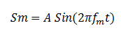
If the message signal is represented by,
Then the equation of amplitude modulation is given by,
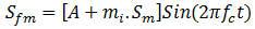
Where ‘mi’ is the modulation index and ‘A’ is the amplitude
Matlab Codes
clc;
clear all;
close all;
t=0:0.001:1;
set(0, defaultlinelinewidth', 2);
A=5;%Amplitude of signal
fm=input('Message frequency=');%Accepting input value
fc=input('Carrier frequency=');%Accepting input value (f2>f1)
mi=input('Modulation Index=');%Modulation Index
Sm=A*sin(2*pi*fm*t);%Message Signal
subplot(3,1,1);%Plotting frame divided in to 3 rows and this fig appear at 1st
plot(t, Sm);
xlabel('Time');
ylabel('Amplitude');
title('Message Signal');
grid on;
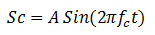
Sc=A*sin(2*pi*fc*t);%Carrier Signal
subplot(3,1,2);
plot(t,Sc);
xlabel('Time');
ylabel('Amplitude');
title('Carrier Signal');
grid on;
Sfm=(A+mi*Sm). *sin(2*pi*fc*t);%AM Signal, Amplitude of Carrier changes to (A+Message)
subplot(3,1,3);
plot(t, Sfm);
xlabel('Time');
ylabel('Amplitude');
title('AM Signa');
grid on;Generated AM Signal
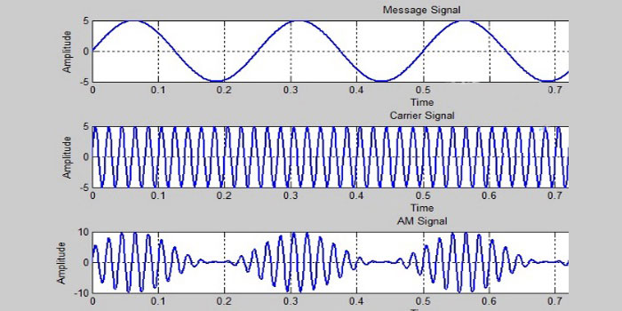
The uses of this particular MATLAB code are also given in the commented form (%comment field). The program is capable of accepting two input frequencies and modulation indexes from the keyboard.
Conclusion
Here we’ve discussed the development process of different types of transmitters along with the basic principles, diagrams, and simulations. To understand these transmitters you’ll only need to understand the basic concept of the multivibrator. We’ve demonstrated how you can use the Matlab code and functions for these transmitters. For this, you’re provided with the complete Matlab codes in this article. So, we hope, now you’ve understood the modulation system in transmitters after reading this article, and you can now make your own circuit for your school projects by implementing these functions described above.
- 1. Simple 555 Timer AM Transmitter Circuit Schematic for Science Fair Project
- 2. Most Simple FM Transmitter Circuit Diagram | With Design & Troubleshooting
- 4. Simple FM Transmitter Circuit Using VMR6512 | HI-FI Audio FM Transmitter Module | Long Range, Short Range
- 6. Matlab Code for Frequency Modulation (FM) With Modulation Index
- 8. MATLAB Code for AM with Modulation Index
- Conclusion
Subscribe to our newsletter
& plug into
the world of circuits
![[Explained] How Long Does It Take a Capacitor to Discharge?](https://www.circuitsgallery.com/wp-content/uploads/2022/12/How-Long-Does-It-Take-a-Capacitor-to-Discharge.jpg)


![What Is Balanced And Unbalanced Output In Op-Amp [Answered]](https://www.circuitsgallery.com/wp-content/uploads/2023/08/What-Is-Balanced-And-Unbalanced-Output-In-Op-Amp.jpg)