What Is Balanced And Unbalanced Output In Op-Amp [Answered]
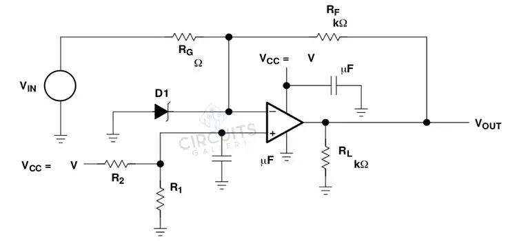
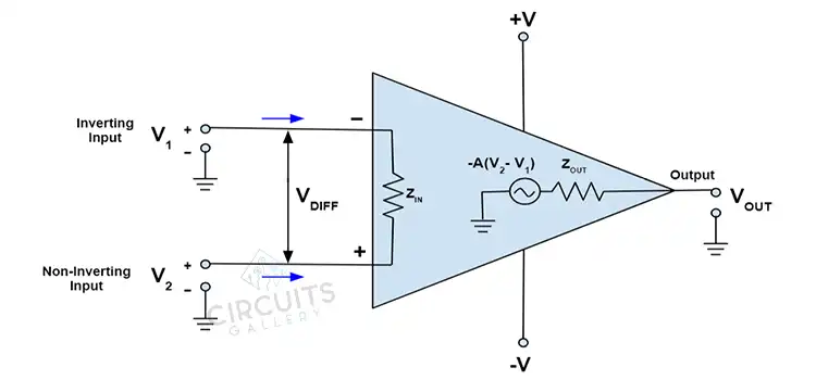
The distinction between balanced and unbalanced outputs in op-amps relates to the symmetry and range of the output voltage swing around a reference point. A balanced output swings both above and below the reference, while an unbalanced output swings in only one direction. Let’s have a detailed glance.
Differential Amplifier And Its Different Classifications
Differential amplifiers are a fundamental building block in analog electronic circuits, used for amplifying the difference between two input signals. They have various configurations based on their characteristics and applications.
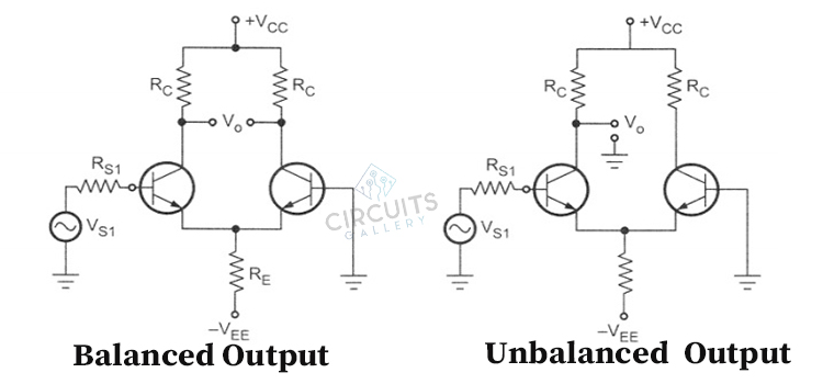
- Dual Input Balanced Output Differential Amplifier
- Dual Input Unbalanced Output Differential Amplifier
1. Dual Input Balanced Output Differential Amplifier
A dual-input balanced Output Differential Amplifier is a circuit designed to amplify the voltage difference between two input signals while keeping the output balanced around a reference point, typically ground. It rejects common-mode signals (equal on both inputs) and responds only to the signal difference.
This amplifier configuration is used in applications requiring accurate amplification of small signals amid noise, making it valuable in precision measurement, communication, and audio systems. Its design typically involves operational amplifiers in a differential setup, along with additional components to achieve the desired characteristics.
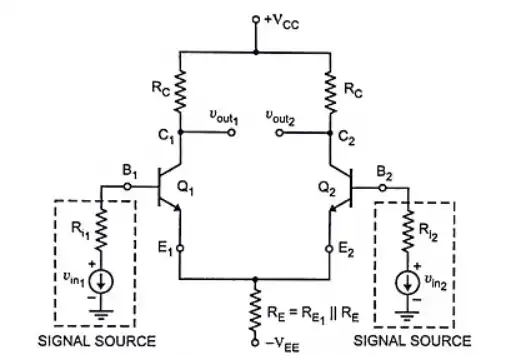
Figure: Dual input balanced output differential amplifier.
DC Analysis
Basically DC analysis has been done in a differential amplifier to find out the operating points when no signal is applied. First of all, we need to determine a dc equivalent circuit of that differential amplifier. If we set both input voltage zero then it can be obtained. To determine the Q point, both transistors are kept identical and also the passive loads ( R1 = R2 = Rc) are the same.
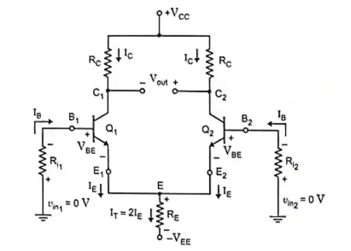
Figure: Equivalent DC circuit of the dual input balanced output differential amplifier.
Now, applying Kirchhoff’s voltage law to the base-emitter loop of the transistor Q1, we get,
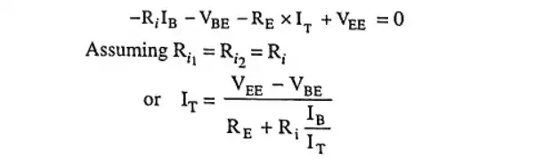
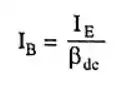
And the base current,
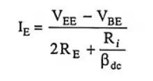
Now, applying Kirchhoff’s current law at node E, we get,
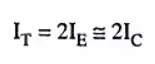
By substituting IT=2IE from equation and IB=IE/dc from equation, we get,
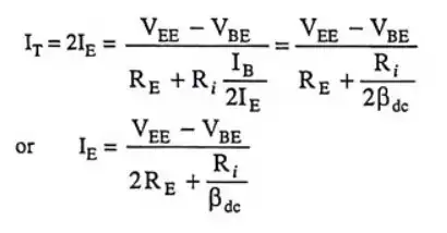
Here, Ri/dc<< 2RE, and therefore we can write the equation as,
We can see that, for a given value of -VEE, the value of RE controls the emitter current in transistors Q1 and Q2. As a result, choosing an emitter resistance RE of the right value will allow one to get the appropriate value of the emitter DC bias current for a particular value of -VEE. As a result, we can see that the collector resistance RC has no effect on the emitter current in transistors Q1 and Q2.
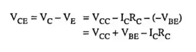
Now, the collector-to-emitter voltage is,
2. Dual Input Unbalanced Output Differential Amplifier
A Dual Input Unbalanced Output Differential Amplifier amplifies the voltage difference between two input signals while providing an output that swings in one direction. This configuration suits applications where the signal varies in one direction and requires amplification accordingly.
It’s important to consider biassing and output range to prevent saturation and distortion. This amplifier is not suitable for signals swinging both above and below the reference point.
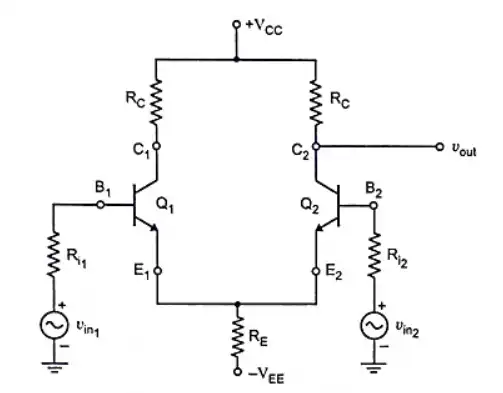
Figure: Dual input unbalanced output differential amplifier.
DC Analysis
The biassing arrangement of the dual input unbalanced output differential amplifier is the same as the dual input balanced output differential amplifier. That’s why the DC analysis is kind of similar in both cases.
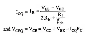
Here the quiescent collector current ICQ and the quiescent collector-emitter voltage VCEQ is defined by the equation given below,
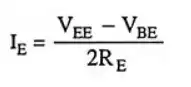
Now, the emitter’s current IE will be,
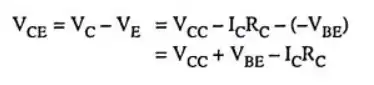
And, The collector-emitter voltage VCE will be,
Frequently Asked Questions
What is the difference between balanced and stereo?
Balanced relates to the way a signal is transmitted to reduce noise, while stereo pertains to audio systems that create a spatial and directional listening experience using multiple channels.
Does balanced output sound better?
Balanced outputs are favored in professional audio due to better noise rejection and signal integrity. They excel in complex setups and challenging environments but might offer fewer benefits in typical home audio with short cable runs.
Can I convert RCA to XLR?
Yes, you can convert RCA to XLR using adapters or converters. Adapters may not address impedance differences, while active converters provide proper signal matching. Consider equipment compatibility and signal quality implications.
Conclusion
Balanced outputs offer bidirectional amplification with reduced noise and distortion, which produces high-fidelity audio. Where the unbalanced outputs simplify circuitry in single-supply systems. Understanding the trade-offs between these options is essential for designing effective and high-quality amplifier systems.
Subscribe to our newsletter
& plug into
the world of circuits
![[Explained] What Is the Unity Gain Bandwidth of 741 Op-Amp](https://www.circuitsgallery.com/wp-content/uploads/2023/08/What-Is-the-Unity-Gain-Bandwidth-of-741-Op-Amp.jpg)