Simple Home Audio Power Amplifier Circuit Schematic
You are now going to be introduced with a new audio power amplifier schematic built around TIP Darlington pair transistors. You can use this circuit for home audio power amplifiers and car audio amplifiers. The TIP142 and TIP147 Darlington pair transistors form a push-pull high power amplifier configuration while the two BC558 PNP transistor provides a mini audio pre-amplifier circuit. The audio signal applies to the pre-amp through a capacitor, coupled to the push-pull power amp via TIP141 transistor. Moreover, we will also provide the values and ratings of different components of power amplifier design. The implementation cost of this mini audio amplifier circuit is too cheap, near $5. Surprisingly, the circuit can deliver 150 W RMS to an 8 Ω (150 Watt power amplifier).
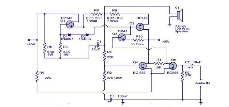
Circuit Diagram of the Audio Amplifier
Components Required
- Transistors (TIP141; TIP142; TIP147; BC558 x 2)
- Resistors 7 watt(0.33Ω x 2)
- Two Resistors 1 watt (3.3kΩ x 2)
- ¼ watt resistors (22kΩ x 2; 220Ω; 1.5kΩ; 33Ω; 27kΩ)
- Capacitors 50V (100µF; 10 µF x 2)
- Speaker (8Ω, 150Watt)
Working of 150 Watt Amplifier
- This audio power amplifier project is based on TIP 142 and TIP 147 (complementary darlington pair power transistors which can handle 5 A current and 100V).
- The two PNP (BC 558) transistors forms a pre amplifier section to the preceding high power push pull amplifier built around TIP141, TIP 142 and TIP 147 darlington pair transistors.
- Moreover, we are using 2 PNP transistors to form a preamplifier section. Actually, it is nothing but a differential amplifier to improve overall performance of the amplifier. The application of a differential amplifier in the input phase reduces noise.
- Input signal is applied to the differential amplifier section via 10µF DC decoupling capacitor. Capacitor removes the DC voltage from the input audio signal.
- 10kΩ potentio meter is for volume controlling.
- Furthermore, feedback voltage is applied through the 22K resistor.
- A complementary class AB push pull power amplifier stage is built around the TIP darlington pair transistors to drive the 8Ω 150 watt speaker (The circuit can deliver 150 W RMS to a 8 Ω).
- The diodes (1N4007) biases the complementary pair and guarantee class AB amplifier configuration.
- On the other hand, transistor TIP141 drives the push-pull pair (TIP142 & TIP147) and its base is directly connected to the collector of pre amplifier stage.
- Finally, +/-40V, 5A dual power supply is necessary to provide supply for this simplest amplifier circuit. Use 30V-0-30V step down transformer and construct a dual lab power supply for this project.
Conclusion
This home audio amplifier circuit can enhance your audio hearing experience. It needs simple components and is easy to implement. So that, this could be a perfect DIY project for your school science fair or to use at your own home.
Subscribe to our newsletter
& plug into
the world of circuits