Simple Portable Audio Power Amplifier Circuit Using lm386 IC
Here circuitsgallery comes with the simplest mini audio amplifier circuit schematic using LM386 low voltage audio power amplifier IC. This circuit is applicable to power medium-sized speakers from a music player that can only drive earphones (lm386 headphone).
The LM386 is a low voltage power amplifier IC designed for use in low voltage consumer applications. It can be used under battery operation and has a wide supply voltage range: 4V–12V or 5V–18V enabling us to use the circuit as a portable amplifier.
Our simple audio amplifier has many applications, the common lm386 projects are AM-FM radio amplifiers, portable tape player amplifiers, intercoms, TV sound systems, line drivers, ultrasonic drivers, small servo drivers, power converters, and much more.
Circuit Diagram of Portable Audio Power Amplifier Circuit
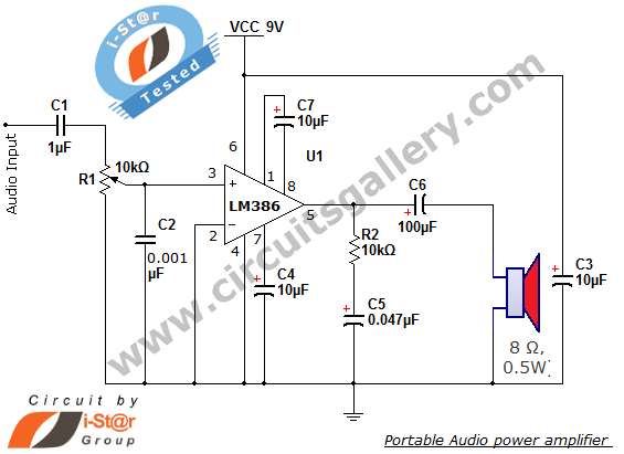
Components Required for Portable Audio Power Amplifier Circuit
- Power supply 9V
- Resistor ¼ Watt (10kΩ)
- Capacitors (1 µ F; 0.001µF)
- Electrolytic capacitors (0.047µF,16V; 10µF, 16V x 3; 100µF, 16V)
- LM386 low voltage audio amplifier IC
- Speaker (8Ω, 0.5W)
Working Principle of Portable Audio Power Amplifier Circuit
- The audio signal is connected to the circuit using a capacitor C1. This capacitor passes only audio and blocks any direct current (DC) that may influence the biasing conditions of the amplifier.
- R1 is a potentiometer, which is used as a volume control for audio signal (simply acts as an attenuator).
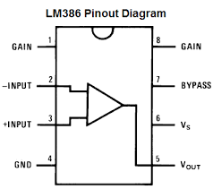
- To make the LM386 a more flexible audio amplifier, two pins (1 and 8) are provided for gain control and gain adjustments. With pins 1 and 8 open, the 1.35 kW internal resistance sets the gain at 20 (26 dB). If a capacitor is placed from pin 1 to 8, bypassing the 1.35 kW internal resistor, the gain will go up to 200 (46 dB).
- The next part is the LM386 low voltage audio power amplifier IC, which amplifies the audio input by means of power from the battery or Vcc supply.
- The resistor R2 and capacitor C5 form a filter circuit, which prevents high-frequency signals coming from the amplifier, most probably noise picked up or generated in the amplifying process of LM386 IC.
- The capacitor C6 connected at the output pin has the same function as the capacitor used in the input stage i.e. to prevent direct current (DC) due to the biasing of LM385 amplifier IC, causing undesired operation of the speaker.
LM386 Pinout
Conclusion
A portable audio power amplifier circuit here operates keeping LM386 at the core. Note that we have used it as a non-inverting amplifier and utilized the 1st and 8th (last) pins for amplification.
Subscribe to our newsletter
& plug into
the world of circuits