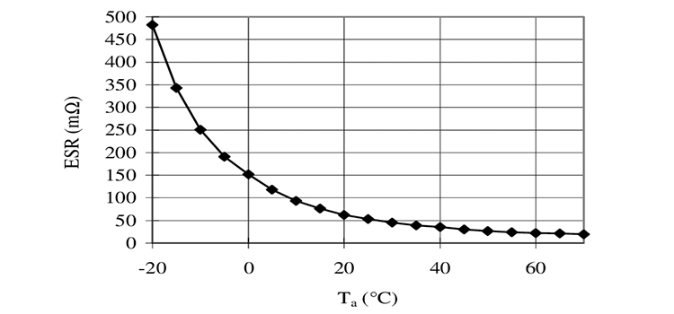
Electrolytic Capacitor ESR Chart
Low ESR capacitors have lower power losses and internal heating issues than high ESR capacitors. High ESR values shorten the life of an aluminum electrolytic capacitor and reduce performance. Furthermore, a low ESR value enables increased ripple current capacity.
ESR(Equivalent Series Resistance), also known as internal resistance, is a number that represents the loss of useable energy in a basic electronic circuit consisting of a resistor and an ideal (perfect) capacitor. Technically, the energy is not wasted but rather dissipated as undesired heat.
Electrolytic Capacitor ESR Chart
Increasing ESR at the input increases high-frequency noise across the capacitor, reducing filtering effectiveness. Higher ESR creates more ripple at the output, impacting the stability of the control loop. ESR is especially essential in low-duty-cycle, high-frequency current pulse applications.
ESR values for ceramic capacitors are typically stated between 0.01 and 0.1 ohms. ESR of a non-electrolytic capacitor is generally stable over time; for most applications, real non-electrolytic capacitors can be viewed as perfect components. You can find the ESR values of various electrolytic capacitors in the chart below:
| 10V | 16V | 25V | 35V | 63V | 160V | 250V | |
| 4.7µF | >40Ω | 35.0 | 29.0 | 24.0 | 19.0 | 16.0 | 13.0 |
| 10µF | 20.0 | 16.0 | 14.0 | 11.0 | 9.3 | 7.7 | 6.3 |
| 22µF | 9.0 | 7.5 | 6.2 | 5.1 | 4.2 | 3.5 | 2.9 |
| 47µF | 4.2 | 3.5 | 2.9 | 2.4 | 2.0 | 1.60 | 1.40 |
| 100µF | 2.0 | 1.60 | 1.40 | 1.10 | 0.09 | 0.77 | 0.63 |
| 220µF | 0.90 | 0.75 | 0.62 | 0.51 | 0.42 | 0.35 | 0.29 |
| 470µF | 0.42 | 0.35 | 0.29 | 0.24 | 0.20 | 0.16 | 0.13 |
| 1000µF | 0.20 | 0.16 | 0.14 | 0.11 | 0.09 | 0.08 | 0.06 |
| 2200µF | 0.09 | 0.07 | 0.06 | 0.05 | 0.04 | 0.03 | 0.03 |
| 4700µF | 0.04 | 0.03 | 0.03 | 0.02 | 0.02 | 0.02 | 0.01 |
| 10000µF | 0.02 | 0.02 | 0.01 | 0.01 | 0.01 | 0.01 | 0.01 |
What Is the ESR of a Capacitor
Equivalent series resistance (ESR) is a non-ideal capacitor property. It can cause several performance difficulties in electronic circuits. Due to I2R losses, noise, and increased voltage drop, a high ESR value reduces performance.
What Is a Good ESR for an Electrolytic Capacitor
The metallic resistance of the leads and electrodes, as well as dielectric losses, create the ESR in non-electrolytic capacitors and electrolytic capacitors with solid electrolytes. ESR values for ceramic capacitors are typically stated between 0.01 and 0.1 ohms.
The lowest ESR capacitors are not necessarily the best option. In certain applications, such as feedback capacitors, too low ESR capacitors may eventually cause some concerns with operating amplifier oscillations outside of operational conditions.
How Do You Calculate ESR on a Capacitor
You can follow different methods to calculate the ESR of a capacitor. The most common ones are illustrated below.
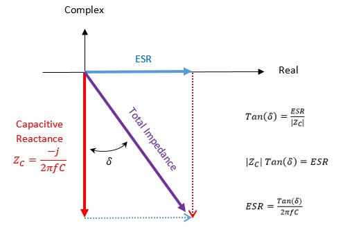
From Loss Angle
On a real-complex plane, the total complex impedance of a capacitor is represented as the vector sum of a real component (the ESR) and a complex (reactive) component representing the ‘ideal’ capacitor that things like ESR mess within all actual components.
The ‘loss angle,’ or angle between the total impedance and its complex component, is a figure used to characterize the ratio between the ideal and non-ideal components of a capacitor’s overall impedance. Perform the following calculation to get the ESR.
From the Ratio of Ripple Voltage to Ripple Current
A simple method for measuring ESR is by the ratio of the capacitor’s ripple voltage to ripple current. However, implementation is both costly and time-consuming.
Under certain conditions, the inductor ripple current might be assumed to be constant, and hence the output ripple voltage dictates the ESR. However, the approach is limited in scope and has low precision.
By Using an ESR Meter
The ESR meter is a reasonably accurate device that is inexpensive and easy to use, particularly when testing many capacitors while they are still in the circuit. In a voltage divider network design, an alternating voltage is provided to the capacitor.
The frequency of the applied alternating current is normally set to a value where the reactance of the capacitor is insignificant. During the ESR meter test, a very short current is sent through the capacitor, causing the capacitor to not charge entirely. The voltage across the capacitor is produced by the current.
Do Electrolytic Capacitors Have Low ESR
During the ESR meter test, a very short current is sent through the capacitor, causing the capacitor to not charge entirely. The voltage across the capacitor is produced by the current. This voltage is the product of the current and the capacitor’s ESR, plus a negligible voltage due to the capacitor’s small charge.
Frequently Asked Questions
What causes high ESR in a capacitor?
The fluid electrolyte is lost over time due to vaporization and diffusion, resulting in a steady decrease in the amount of conducting material, a reduction in the contact area, an increase in ESR, and a decrease in capacitance.
Conclusion
To simulate the behavior of an actual capacitor, further elements must be added to the capacitor model. ESR predicts the converter’s output ripple as well as capacitor lifetime. Hence it is significant while analyzing the dynamic behavior of power converters. The power dissipated in ESR raises the temperature of the capacitor.
Subscribe to our newsletter
& plug into
the world of circuits
![How to Run a 12V DC Motor on 120V AC [Step-by-Step Guide]](https://www.circuitsgallery.com/wp-content/uploads/2023/10/How-to-Run-a-12V-DC-Motor-on-120V-AC.webp)