Single Ended vs Push Pull
A single-ended “class-A” amplifier is less effective than a push-pull amplifier. The output power that can be generated improves the power that is available for a given supply voltage and is more than the continuous consumption rating of either transistor or tube used alone.
Difference Between Single Ended and Push Pull Amplifiers
Push-pull and single-ended output stages are the two primary types used in guitar amplifiers. These phrases describe the “topology” of the amplifier output stage circuit, which describes how the output stage’s constituent parts are connected.
The debate of which one goes over another is going on for years. The connection of the tubes to the output transformer and the kind of transformer employed are the primary differences between single-ended and push-pull circuits.
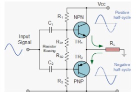
The single-ended amplifier only needs to work in one direction because it has a single driver that is constantly active and running on a bias. But that the complementary transistor pair generating the output of the push-pull amplifier is used when one transistor is either pushing or pulling.
What Are A Single-ended Amplifiers
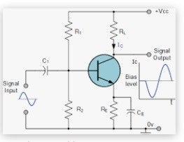
Single-ended refers to exactly that. In simple terms, one power tube handles the entire job. The truth is that single-ended amplifiers may use several parallel single-ended (or “PSE”) power tubes per channel. Power tubes perform identically and handle the entire sine wave shape of the AC music signal jointly.
In other words, they work as a single tube when combined. The single-ended output stage operates in the class A operating class since it must handle the whole waveform. Therefore, it is inclined to carry plate current throughout the entire 360 degrees of the AC signal cycle and keeps the tube all in a very linear part of its operation times.
The iconic Fender Champ guitar amplifier and innumerable early radios and televisions both employ the single-ended stage as their output stage. The single-ended triode stage, which is said to be the “ultimate” in hi-fi sound reproduction, is making a resurgence in high-end vacuum tube audio.
Disadvantages
When compared to push-pull output stages, it produces extremely low power levels and is equally as inefficient as it is musical. The transformer for this kind of stage must be able to withstand a constant DC current, which is another issue.
Single-ended has several drawbacks including no rejection of even order harmonics, no rejection of power supply hum, often asymmetrical limiting on overloads, which intensifies even order harmonics, and no rejection of even order harmonics.
Compared to the push-pull output stage, these “drawbacks” give the single-ended output stage a distinctive tone. Whether it is better or not depends on personal preference. Some guitarists choose push-pull output stages, while others favor single-ended output stages.
What Are the Advantages of Using a Push-Pull Amplifier Over a Single-Ended Power Amplifier
In terms of performance and distortion, push-pull amplifiers outperform single-ended amplifiers. No matter how well-designed it is, a single-ended amplifier will unavoidably exhibit some distortion because of the nonlinear dynamic transfer characteristics of the device.
In applications where minimal distortion, high efficiency, and high output power are required, push-pull amplifiers are frequently utilized. When a signal is divided, the input coupling transformer is set up so that one signal is applied to one transistor’s input and the other signal is applied to the input of the other transistor.
Push-pull amplifiers have low distortion, no magnetic saturation in the coupling transformer core, and the ability to cancel power supply ripples, which eliminates hum. However, they also require two identical transistors and large, expensive coupling transformers, which are drawbacks.
Can I Use a Push-Pull Output Transformer in a Single-Ended Amp
Yes, you can. At idle, a P-P transformer may carry the same amount of bias current per watt of output as a single-ended transformer. The SE transformer would have two tubes running in Class A; however, due to the inverted signal, instead of one tube’s current increasing, the other would decrease.
The Class A P-P transformer would have twice the idle current of a SE transformer, but it would also be rated for twice as much power (twice the watts) because it would be sized to output the power of two tubes.
The SE transformer will operate at half the current and produce half the amount of magnetizing current the core can handle if the transformer is sized to the tube, whereas in the P-P case, the two idle currents are traveling in opposite directions, creating two magnetic fields that are in opposition to one another and cancel each other out.
Requirement
If you measure the tube’s idle current, feed it via the center tap along with an equal amount to the opposite end of the “unused” winding, and add a load resistor that consumes the same amount of idle current as the tube, P-P transformers can function in a SE configuration.
It is unpleasant to just take a push-pull OT and run it at lower power as a single-ended transformer due to other differences such as an air gap. A push-pull OT in a single-ended circuit can be utilized in an emergency. There will be noise.
Why Push-Pull Amplifier Is Used
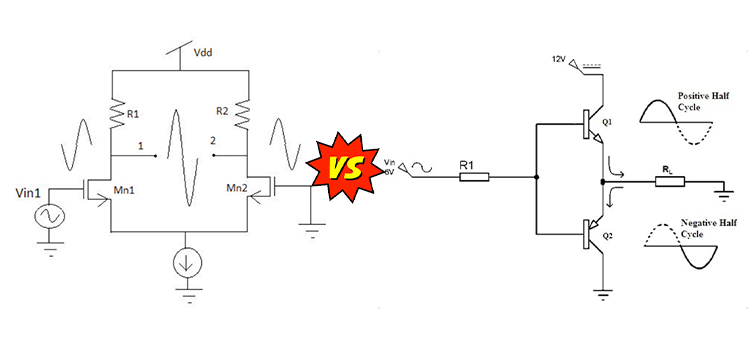
An amplifier that features an output stage that can drive a current through the load in either direction is referred to as a push-pull amplifier. A typical push-pull amplifier’s output stage is made up of two identical BJTs or MOSFETs, one of which sources current through the load and the other of which sinks it.
A push-pull amplifier’s fundamental mode of operation is as follows: First, two identical signals that are 180 degrees out of phase are created from the signal to be amplified. In most cases, an input coupling transformer is used to accomplish this splitting.
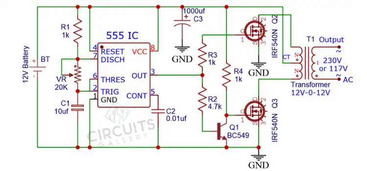
In a push-pull amplifier, the power supply is linked to the transformer’s center-tap, and the upper and lower ends of the center-tapped primary are each connected to a tube.
Advantages
For a push-pull stage to function, at least two tubes must be connected to each side in parallel; however, for greater power amps, up to eight output tubes may be used. “Parallel push-pull” operation is what is meant by this.
Another benefit of the push-pull circuit is that, if the tubes are matched and the output stage is balanced, there is little to no unbalanced DC current in the output transformer because the current travels in the opposite directions to each tube, allowing a smaller transformer with less iron. The output stage’s order harmonics and distortion products are also eliminated.
Conclusion
The major reason for using push-pull amplifiers over single-ended is their higher efficiency. However, there are some people who prefer single-ended amplifiers due to their simplicity.
Subscribe to our newsletter
& plug into
the world of circuits
![LCD Ribbon Cable Repair Methods | [3 Fixes Detailed]](https://www.circuitsgallery.com/wp-content/uploads/2024/04/LCD-Ribbon-Cable-Repair-Methods.webp)