Inverter Circuits Using 555, PIC, PWM, or MOSFET
We all know what an inverter is and the importance of this device. It simply converts low DC power into high AC power. AC can’t be stored for future use, but you can store DC power in a battery for future use. The stored DC can be converted back to AC by using power inverters that can be used as the power source during a power outage.
As this is a useful device for every place like homes, schools, and offices, it would be beneficial to you if you can make one at a low cost. If you are interested in making an inverter circuit, then you are at the right place. Because we are going to show you how easily you can make an inverter circuit using some simple and common ICs.
In this article, we have demonstrated the making and working process of inverters using four different components. Here is the list of those inverters-
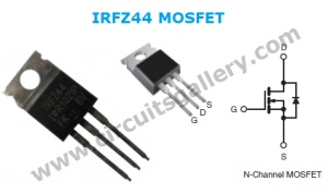
- Simple low-power inverter circuit using CD4047 and IRFZ44 power MOSFET.
- 12v DC to 220V AC inverter circuit using PWM IC SG3525.
- Inverter circuit diagram using 555 timer IC.
- Simple PWM DC to AC voltage inverter circuit based on SG 3524 IC.
All of them are easy to make, and you can use them in your home during a power outage. So, what are we waiting for? Let’s read by the end of this article, choose any of them and build your own inverter.
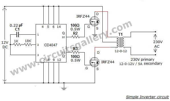
1. Simple Low Power Inverter Circuit | 12v DC to 230v or 110v AC | Using CD4047 and IRFZ44 Power MOSFET
This simple low-power DC to-AC inverter (DC to AC converter) circuit converts 12V DC to 230V or 110V AC. You can use this to supply electricity to the electric bulb, CFL, etc. in your home during electricity failure. If you want to convert 6V DC to 230V AC or 110V AC, then you have to do some simple modifications to this inverter.
You can build the circuit of this simple inverter at a cheap rate with locally available components such as a 12V rechargeable battery and battery charging circuit.
Circuit Diagram of DC to AC Inverter Circuit
Components Required for DC to AC Inverter
- IC CD4047
- Resistors (1K, 18K, 100Ω- 0.5W x 2)
- Capacitor (0.22µF)
- 12V rechargeable battery
- Battery charger circuit
- IRFZ44 MOSFET x 2
- Step Down Transformer (230V primary 12V-0-12V, 5A secondary) (110V to 12V-0-12V, 5A can also be used) NB:- Transformer connection inverted
Circuit Connections of DC to AC Inverter
- You must use a battery and battery charger to implement this inverter circuit.
- The inverter circuit is built around IC CD4047 which is wired as an astable multivibrator.
- The operating frequency of astable multivibrator is set to 50Hz.
- The power MOSFETs (the two IRFZ44) are directly driven by the Q and Q’ output of CD4047. They are pin 10 and 11 respectively.
- The power MOSFETs are connected in a Push-Pull configuration (Power amplifier). Here the MOSFETs will switch according to the pulse from CD4047 astable multivibrator.
- Thus, an AC voltage is transferred to the primary transformer; it is stepped up to 230V.
- The transformer used here is an ordinary step-down transformer which is connected in an inverted manner. That is, the primary of a 230V to 12V-0-12V step-down transformer can be treated as secondary for this inverter project.
- If you would like to get 110V AC, choose 110V to 12V-0-12V step-down transformer in a reversed way. (That is primary as secondary and secondary as primary)
- Use suitable heat sinks for MOSFETs.
Here is the tested and verified inverter circuit that I have made, for those who doubt the working of the circuit.
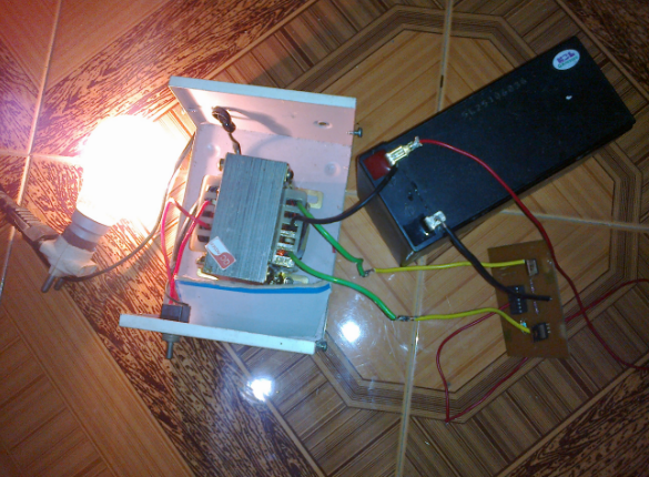
Now, you’re free to convert quite any level of DC source to standard AC voltages (230 or 110) using this inverter. Besides, multi-tap transformers will allow you to input more voltages. You can learn more about adjusting voltage from power supplies.
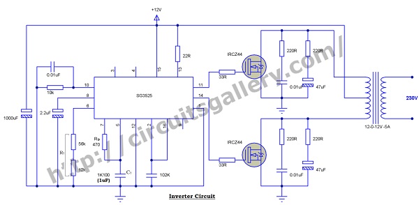
2. 12v to 230v Inverter Circuit Using PWM IC SG3525 | 100 Watt Inverter Circuit Diagram
We have demonstrated the process of making a 12v DC to 230v AC inverter circuit using PWM IC SG3525 which is one of the best inverter efficiency. Here you need to use mainly the internal oscillator of PWM SG3525. So, let’s see the detailed making process of this inverter including the diagram below.
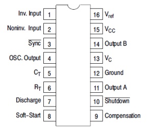
Features of IC SG3525 SMD
SG3525 IC is a pulse-width modulator integrated circuit. Its specialties include-
- Wide operating voltage range from 8 to 35V
- Inbuilt oscillator and frequency range 100HZ to 500KHz
- Input and output synchronization terminals
- Variable dead time controller
- Soft-start facility
- Smooth shut-down facility
- Input voltage checking facility
- Dual source/sink output driver
Single Phase Inverter Circuit Diagram
Components Required
- SG3525 IC
- MOSFETS IRF Z44 x2
- Resistors (22,10K,56K,12K,470,33×2,)
- Resistors(220×4 ½ watt)
- Capacitor (0.01uFx3, 1000uF/25V ,2.2uF/25V ,1K100,102K, 47uF/25Vx2)
- Transformer 12-012V /5A step-down transformer (we will use as step-up)
Working Principle of 100 Watt Inverter Circuit
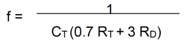
- SG3525 has an inbuilt oscillator. Its frequency can be determined by connecting the capacitor and resistor on pin 5 and pin 6 respectively.
- The frequency of oscillation can be calculated by the equation:
- Output is taken from pins 11 and 14 which are connected to the gates of Mosfets.
- Pins 11 and 14 operate as totem pole configurations or in a push-pull manner. It never turns ON two pins at the same time.
- The signal from two pins 11 and 14 are connected to the gates of power MOSFETs IRF Z44. They switch current to each winding of the transformer.
- Only one winding is activated at a time and both are energized in opposite directions.
- Activation of winding in opposite direction helps to produce an alternating EMF. Thus it produces alternating current (AC) on the secondary of the transformer too.
- The frequency of the output AC is 50Hz which is determined by the CT and RT pins of SG3525(pin 5 and 6).
Components Pin Out
Building a 12v to 230v inverter circuit using PWM IC SG3525 is an efficient way of getting AC power from a DC power source. It may take you some time to get familiar with pulse width modulation ICs. But the simulation and designing of the circuit are quite easy.
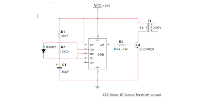
3. 555 Timer IC Inverter Circuit Schematic | 12v to 220v DC-AC Converter
Here we have demonstrated the simple inverter circuit diagram using a 555 timer IC. The astable multivibrator mode operation of 555 timers is utilized here for AC oscillations and these oscillations are switched via transistor 2SC4029 to a transformer. The transformer steps up the voltage to 220V AC. You simply need a 12V battery and a battery charger circuit for this project. Check the section below for more details about this inverter circuit.
Circuit diagram of DC to AC inverter
Components required for 555 timer IC inverter circuit
- Power supply (12V)
- Resistors (3kΩ x 2; 1kΩ, 2W x 1)
- Capacitor (10µF)
- 555 timer IC
- Diode(1N4007)
- Transistor (2SC4029)
- 9V to 220V Step up transformer
Working of DC to AC inverter using 555 timer
- This is a simple inverter circuit based on 555 timer IC. Here timer IC is wired as an astable multivibrator mode.
- We have already discussed Astable multivibrator using 555. Here the oscillation frequency is set to 50Hz supply frequency in India.
- The diode 1N4007 is used to get a 50% duty cycle for the pulses from 555, it also reduces the design complexity.
- The output pulse from the 555 astable multivibrator is fed to the base of power transistor 2N5192. The 2N5192 transistor works as a switch, so the 12V DC supply passed through the transformer at a rate of 50 times per second.
- The transformer step up the 12V to 220V, thus we got 50Hz, 220VAC supply at the output of the transformer secondary.
- Use a 12V battery along with a battery charger circuit to power this DC to AC inverter.
Design of a 12V to 220V 555 Timer IC Inverter Circuit Schematic
For a 555 timer stable multivibrator designed to oscillate at 50Hz, the line frequency can be calculated easily. The Frequency of astable multivibrator is given by,
Choose C = 10µF
then
Use R1= R= 3kΩ
555 timer IC Pinout
Using a 555 timer IC inverter circuit can be a game-changer in reducing bulkiness. In many cases, installing 12V batteries is quite difficult with buck-boost circuits. 555 timers can help a lot in that regard.
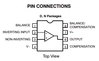
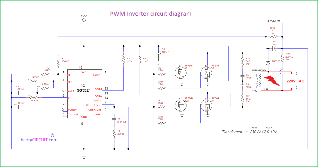
4. Simple PWM Inverter Circuit Diagram Using PWM Chip SG3524
In this section, we have discussed a simple PWM DC to AC voltage inverter circuit based on IC SG 3524. The SG3524 IC chip is a fixed frequency PWM (Pulse Width Modulation) voltage regulator control circuit, with indifferent outputs for single-ended or push-pull applications.
You can find all the functions necessary for the production of a regulating power supply, electrical inverter, or switching regulator on this SG3524 IC integrated circuit as a single chip. Moreover, it can be used as the control element for high-power output purposes
Can you remember the PWM theory? If the greater the control voltage, the wider is the resultant pulses. Using a sinusoidal frequency as the control voltage for pulse width modulator circuits, it is likely to generate a high-power waveform whose average voltage varies with the sine wave, which is suitable for driving ac loads.
Let’s check out this powerful inverter circuit below.
PWM Chip SG3524 Application Notes
- Regulating power supply.
- Electrical inverter or switching regulator on a single chip.
- Transformer-coupled dc-to-dc converters.
- Transformer-less voltage doublers, and polarity-converter applications employing fixed-frequency, pulse-width modulation (PWM) techniques.
- The complementary output allows either single-ended or push-pull applications. Each device includes an on-chip regulator, error amplifier, programmable oscillator, pulse-steering flip-flop, two uncommitted pass transistors, a high-gain comparator, current-limiting, and shutdown circuitry.
Circuit Schematic of PWM Inverter
Components Required
- Power supply (12 V)
- Resistors (10kΩ; 4.7kΩ x 2; 100kΩ x 2; 1kΩ, 1W x 3; 100Ω x 2; 20kΩ; 0.1Ω; 200kΩ,2W)
- Electrolytic capacitors (0.1µF x 2; 0.001µF; 1µF; 100µF)
- PWM chip IC3524
- Transformer (12-0-12 V primary, 220V secondary)
Working of PWM Inverter Circuit
- The IC SG3524 operates at a fixed frequency, the oscillation frequency is determined by one-timing resistor RT and one-timing capacitor CT.
- RT set up a constant charging current for CT. So there exists a linear ramp voltage at CT, which is connected to the comparator.
- The comparator provides linear control of the output pulse width (duration) by the error amplifier.
- The SG3524 contains an inbuilt 5V regulator that supplies a reference voltage, also providing the SG3524 internal regulator control circuitry.
- The inside reference voltage is divided on the outside by a resistor network to give a reference to the inbuilt error amplifier. (External reference can also be used).
- The output is sensed by a subsequent resistor divider network and the error signal is amplified. This voltage is then compared with the linear voltage ramp at timing capacitor CT, thus producing a pulse width modulation (PWM) pulse.
- The resultant PWM pulse from the comparator is passed to the corresponding output pass transistor (Q1, Q2 refer block diagram) using the pulse steering flip flop, which is synchronously toggled by the oscillator output.
- The oscillator output pulse also acts as an inhibiting pulse to make sure that both the transistors are never turned ON simultaneously. The duration of this pulse is determined by the value of CT.
- Pin 11 and 14 connect the TIP transistor for driving the transformer. T1 is a 12-0-12 V primary, 220V secondary, 300VA transformer.
- When the signal at pin 14 is high, the upper transistor is ON and current flows from the +12V source via the upper half of the transformer to the ground.
- When 11 of the IC pin goes high, the lower transistor gets switched ON and current flows from the +12V source via the lower half of the transformer primary and sinks to the ground.
- Thus, we got positive and negative half cycles of 220V AC supply.
Now you can simply make your own fabricated PWM Inverter circuit using SG 3524 IC. It is easy to operate which can make it a perfect inverter for any project.
Conclusion
Four different methods to make a powerful DC to AC inverter are demonstrated above, and we hope, now you can make your own fascinating inverter after following this guide. If you have built an inverter using CD4047 and IRFZ44 power MOSFET and need more voltage from your inverter then you can use the multi-tap transformers to modify that inverter. You can also try the 555 timer instead of other buck-boost circuits to reduce the bulkiness of your inverter. If you have any queries regarding this topic, don’t hesitate to ask in our comment section below.
- 1. Simple Low Power Inverter Circuit | 12v DC to 230v or 110v AC | Using CD4047 and IRFZ44 Power MOSFET
- 2. 12v to 230v Inverter Circuit Using PWM IC SG3525 | 100 Watt Inverter Circuit Diagram
- 3. 555 Timer IC Inverter Circuit Schematic | 12v to 220v DC-AC Converter
- 4. Simple PWM Inverter Circuit Diagram Using PWM Chip SG3524
- Conclusion
Subscribe to our newsletter
& plug into
the world of circuits
![What to Do With Red Wire if Not Needed [Unraveling the Mysteries]](https://www.circuitsgallery.com/wp-content/uploads/2023/07/What-to-Do-With-Red-Wire-if-Not-Needed.jpg)

![Arduino Uno Programmer Not Responding [Troubleshooting Guide]](https://www.circuitsgallery.com/wp-content/uploads/2023/12/Arduino-Uno-Programmer-Not-Responding.webp)