Multivibrator Circuits and Calculators for Digital Control | 555 Timer Projects
You may be familiar with the multivibrator which is an electronic circuit that generates square, rectangular, and pulse waveforms, which are also known as nonlinear oscillators or function generators. It’s basically a two-amplifier circuit arranged with regenerative feedback.
Now, let’s make some multivibrator circuits and calculators for digital control projects. In this article, we are going to show how you can make –
- A monostable multivibrator which is a triggerable pulse generator that produces a single pulse upon receiving a trigger.
- An astable Multivibrator that is capable of producing sharp continuous square waves and also, a free-running oscillator or simply a regenerative switching circuit using positive feedback.
- An astable frequency calculator tool.
You can make all of these using some simple components such as 555 timers and transistors. So, without any further ado, let’s learn how to make multivibrator circuits and calculators for digital control below.
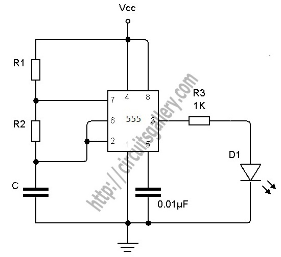
1. Astable Multivibrator Using NE 555 Timer IC | Circuit Diagram and Working Principle
An astable Multivibrator is nothing but an oscillator circuit that produces continuous pulses. You can make an Astable Multivibrator using 555 timer IC, Op-Amps, and also using transistors. The 555 IC provides accurate time delay from milliseconds to hours. It is suitable for circuit designers with a relatively stable, cheap, and user-friendly integrated circuit for both monostable and astable applications.
You can also control the frequency of oscillation by simple modification with this project. The frequency can be controlled by changing the values of R1, R2, and C1. Let’s learn more about this simple 555 timer circuit project below.
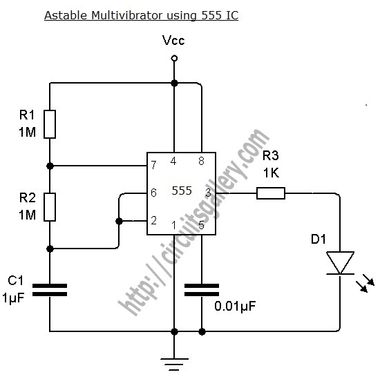
Components for Astable Multivibrator Using NE 555 Timer IC
- NE 555 or SE 555
- Resistor (1MΩx2, 1KΩ)
- Capacitors (0.01µF, 1µF)
- LED
Circuit Diagram of Astable Multivibrator
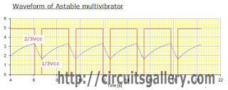
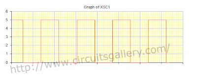
Output Waveform of Astable Multivibrator
Design of Astable Multivibrator
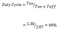
Capacitor charges through R1 and R2. Therefore, charging time is given by Tcharge=0.69(R1+R2)C1. During this time the output is High. So,
Tcharge=Ton=0.69(R1+R2)C1=1.38 sec
The capacitor discharges through R2 only there for discharging time is given by Tdischarge=0.69 R2 C1. During this time the output is low. So,
Tdischarge=Toff =0.69 R2 C1=0.69 sec
Time Period=Ton+Toff=2.07sec
Frequency of oscillation=.483Hz
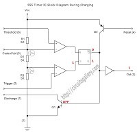
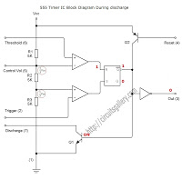
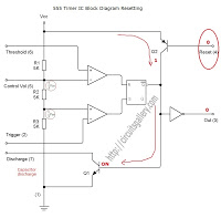
Working Principle of NE 555 Timer | Charging, Discharging and Resetting
Working Procedure of Astable Multivibrator
- Consider the flip-flop is initially cleared. When the power is switched on, the output of the inverter will be HIGH.
- Now the capacitor C1 starts charging through R1 and R2. (Discharge transistor Q1 is OFF)
- When the capacitor voltage exceeds 2/3 Vcc, the upper comparator output will be High, it Reset the control flip-flop.
- So the Q output of the control flip-flop will be LOW and Q’ will be High. So the final output from Inverter is LOW
- At the same time, the discharge transistor Q1 turns ON and the capacitor starts to discharge through R2
- When the capacitor voltage is less than 1/3 Vcc, the lower comparator output will be high, then the control flip-flop gets set to High. (Q=1, Q’=0, Final output=1)
- Now the discharge transistor Q1 is OFF and then the capacitor starts charging. This process continues.
- The LED connected to the output will glow according to the output status.
- 4th pin is the Reset pin, a Low voltage at this pin resets the IC. The Low signal is applied to the base terminal of reset transistor Q2. Then it turns ON followed by Discharge capacitor Q1 and capacitor discharges. See the images below.
Plenty of projects require periodic operations. An astable multivibrator paves the way to control and drive any of such electronic projects. We hope, this explanation of astable multivibrator will surely make designing easier for you.
2. Astable Multivibrator Using Transistors | Transistorised Circuit Wave Form and Operation
The Astable Multivibrator is a cross-coupled transistor network that switches continuously between its two unstable states without needing external triggering. The time period of the astable multivibrator can be controlled by changing the values of feedback components such as coupling capacitors and resistors.
We have also explained the NE 555 IC-based astable multivibrator circuit. Here we are dealing with a modified version: Transistorised Astable Multivibrator.
Circuit Diagram of Transistorised Astable Multivibrator
Components Required for Astable Multivibrator Using Transistors
- Resistors (1KΩx2, 1MΩx2)
- Capacitors (1µFx2)
- Transistors (BC548x2)
- LEDs
- DC power supply
Working Principle of an Astable Multivibrator Using Transistors
- Assume anyone of the transistors Q1 or Q2 turns ON due to parameter variation or due to some switching transients. Let it be Q1.
- Then the collector voltage of Q1=Vce(sat)=0.2V, it is cross coupled to base terminal of Q2 through C1, then Q2 remain in OFF state.
- During Q1 ON, the current path through R1 charges the capacitor C1, the capacitor C1 voltage is coupled to base of transistor Q2.
- While charging C1, when the capacitor voltage exceeds 0.7V, Q2 turns ON.
- As soon as Q2 enters the ON state, its collector voltage falls to Vce(sat)=0.2V. It is coupled to the base terminal of Q1 and so Q1 turns OFF.
- At the same time capacitor C2 starts charging through R2. When the voltage of C2 exceeds 0.7 V, Q1 turns ON due to cross-coupling.
- This process continues.
- We can also take the output from the collector terminals of the transistors. Such variation of the circuit is shown below.
- To know the working of the circuit below you must know how the transistor acts as a switch.
Output Waveform
The following is the output taken from the collector terminal of Q1.
Generalized Design of Transistorised Astable Multivibrator
If the reference transistor is Q1, the time period of the positive cycle of transistorized astable multivibrator is given by,
Ton=0.69 R1xC1 sec
Toff=0.69R2xC2 sec
We can also take the output from Q2. Then,
Ton=0.69 R2xC2 sec
Toff=0.69R1xC1 sec
My Design of Transistorised Astable Multivibrator
I designed the circuit for 0.6 sec ON and 0.6 sec OFF.
Assume C1=C2=1µF
Then R1=R2=1MΩ
So,
Ton=0.69x1MΩx1µF=0.69 sec
Toff=0.69x1MΩx1µF=0.69 sec
Time Period (T)
T=Ton + Toff
= 0.69 (R1C1+R2C2)
Frequency (F)
Duty cycle (D)
Implementation of Astable Multivibrator Using Transistors in Breadboard
BC548 is the most common BJT used in an electronics project. If you are an electronics enthusiast, you must understand it well and know sufficient uses of it. It will make “building an astable multivibrator using transistors” much easier for you.
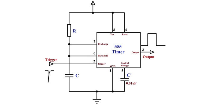
3. Monostable 555 Multivibrator Working Principle and Circuit Diagram With Animation & Components Pinout
In this section, we’re going to demonstrate a monostable 555 timer multivibrator circuit, which is known as a one-shot monostable multivibrator. It is a re-triggerable mono-shot pulse generator multivibrator.
The name ‘Mono stable’ indicates that it has only one stable state. The unstable state is called the ‘Quasi stable state’.The charging time constant of the RC network determines the duration of the stable state or the pulse width. We will show you can transfer the multivibrator from a stable state to a quasi-stable state by a pushbutton trigger switch. The animated (simulated) monostable555 multivibrator working principle is illustrated with proper explanations below.
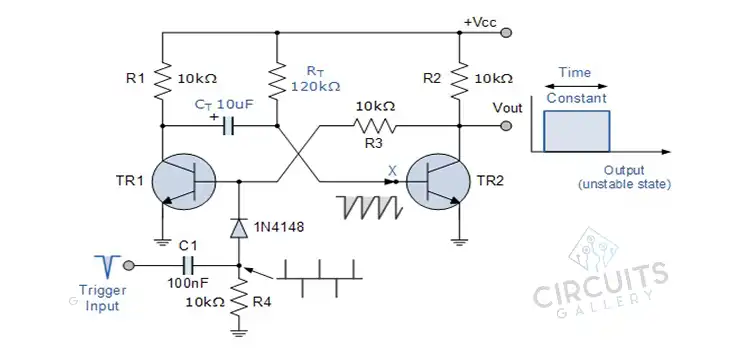
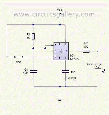
Circuit Diagram of Monostable Multivibrator
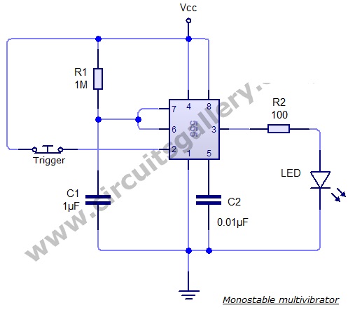
Components Required for Monostable 555 Multivibrator
- 555 timer IC
- Resistors (1MΩ, 100Ω)
- Capacitors (1µF, 0.001µF)
- LED push button switch
Monostable 555 Multivibrator Working Principle
- The output of the monostable 555 multivibrator remains in its stable state until it gets a trigger.
- Primarily the transistors and capacitors are shorted to ground. This state is considered the stable state of the monostable 555 multivibrator.
- As we know, when the voltage at the second pin of 555 IC goes below 1/3 Vcc, the output becomes high. The high state is known as the ‘Quasi stable state’. (Refer to Astable multivibrator using NE 555)
After Triggering the Monostable 555 Multivibrator
- The trigger causes the transition from a stable state to Quasi stable state.
- So when we press the button (Trigger), the voltage at the 2nd pin becomes less than 1/3 Vcc (Disconnected from Vcc). Hence, the output turns high.
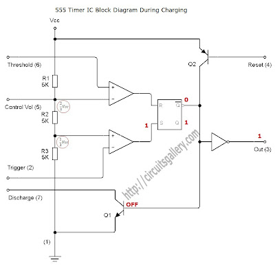
- Then the discharge transistor is cut off and the capacitor starts charging towards Vcc (Refer to the internal circuit of NE555). Charging of the capacitor is done through the resistor R1 with a time constant R1C1.
- As the capacitor voltage increases and finally exceeds 2/3 Vcc, it will reset the internal control flip-flop, thereby turning off the 555 timer IC. (more than 2/3 voltage at the threshold pin (6th pin) causes IC to reset).
- Thus the output goes back to its stable state from Quasi stable state.
Design Equation for Monostable Multivibrator
On-time, Ton = 1.1 * R1C1
Simulation of Monostable Multivibrator
Internal Circuit of 555 Timer IC
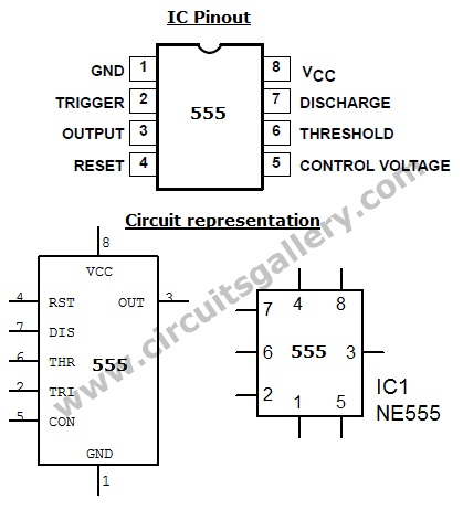
555 Timer Pin Out
A monostable multivibrator is mostly used for the delay and/or memory operations. And 555 timer IC is the most cost-effective and efficient component. Thus, understanding the monostable 555 multivibrator working principle will help you build this project more easily.
4. 555 Timer Astable Calculator for Astable Multivibrator Designing
You already know that the oscillation frequency and time period of an astable multivibrator can be manually controlled through simple modification of resistors and capacitors i.e. by changing the values of R1, R2, and C1. Furthermore, you can use a 555 timer astable calculator for this project. Let’s learn more about this astable calculator below.
555 Calculator for Calculating Frequency and Time Period
We had already discussed the working of 555 timer astable multivibrator in detail with animation. Though we provided the design equation there, one of our readers Mr. Dewanto asked “I need Ton=3 seconds, and Toff= 15 minutes. how can I modify the capacitor then?”. So we thought about creating an astable 555 timer calculator. With this 555 timers IC astable calculator, you can calculate frequency, duty cycle (in percent), and high and low output time periods to meet your requirements.
| Astable Calculator | ||
| R1: R K M | R2: R K M | |
| C: uF nF pF | ||
| T1 High output (Sec) | ||
| T2 Low output (Sec) | ||
| T1 + T2 Period (Sec) | ||
| Frequency (Hertz) | ||
| Duty Cycle (Percent) | ||
Reference Circuit Diagram of Astable Multivibrator Using 555 Timer
5. 555 Timer Monostable Calculator for Monostable Multivibrator
As you are already aware of the working procedures of the monostable multivibrator from the previous sections of this article, it will be easier for you to understand the monostable calculator.
The monostable calculator is intended to give the pulse duration (delay) for the one-shot timer 555. The control capacitor and resistor determine the duration of the stable state or the pulse width.
Once you trigger the 555 timers one-shot circuit, the output goes high and stays there for some time (T=1.1 R C) and then returns back to ground level. You can get the capacitor and resistor from a time-constant RC for this circuit.
To make this 555 timer calculator, carefully read and follow the instructions from the section below.
555 Monostable Calculator Tool
| Monostable Calculator | |
| Resistor: Ohm K M | |
| Capacitor: uF nF pF | |
| Duration of Pulse (sec): | |
How to Use Monostable 555 Timer Calculator?
It is very easy to use this tool for finding out the pulse duration of re-triggerable one-shot 555. Input the values of the resistor and capacitor, then click calculate button. That’s all…!
Reference Circuit Diagram
Conclusion
Multivibrators are often used as the timing control of electronic projects. Though you can find many other alternatives in this context, they aren’t often the cheapest solution. This guideline will help you realize an astable multivibrator using the 555 timer IC with all associated basics and knowhows. Furthermore, understanding the 555 timer is at the heart of this endeavor. If you found this guide helpful for your electronic projects or if you’re having any confusion in your mind regarding the mentioned topics, feel free to leave a comment below. Best wishes for your upcoming project.
- 1. Astable Multivibrator Using NE 555 Timer IC | Circuit Diagram and Working Principle
- 2. Astable Multivibrator Using Transistors | Transistorised Circuit Wave Form and Operation
- 3. Monostable 555 Multivibrator Working Principle and Circuit Diagram With Animation & Components Pinout
- 4. 555 Timer Astable Calculator for Astable Multivibrator Designing
- 5. 555 Timer Monostable Calculator for Monostable Multivibrator
- Conclusion
Subscribe to our newsletter
& plug into
the world of circuits

