Circuit Diagram of Mosfet Power Amptop | 10 Simple 555 Timer Projects Kits for Students
Today Electronic projects for school students are an essential part of their academics. These educational science experiments for kids boost their skills and analytic power rapidly to a great extent. But most of the parents and students worry about how to make science projects for school. By considering this situation, here are some of the awesome 555 timer projects kits for students.
The 555 timer IC is one of the widely used low-cost and highly stable ICs among many electronic components and different kinds of timers. The main applications of 555 ICs are Square wave generation (Astable multivibrator) and single pulse generation (Monostable multivibrator).
Typical 555 timer IC can provide time delays from milliseconds to hours. Signetics introduce it in 1971. Today in an approximate calculation around 1 billion units are manufactured per year. Due to the unique features, 555 timer IC is found in many hobby circuits, moreover, electronics beginners can start their workshop easily on this timer IC. So here we are going to give you the simplest top ten 555 timer IC projects for school students and electronics hobbyists. Moreover, you will also find detailed descriptions of the top 555 timer projects working. These projects are also top 555 timer projects for beginners.
1. Electronic Mosquito, Insect Repellent Circuit Using 555 IC

555 timer is a perfect oscillator when it is configured as an Astable multivibrator. In this mosquito repellent circuit, we are making use of certain frequencies to drive away from the mosquitoes. Insects can be prevented by special spectra of audio sound frequencies in the ultrasonic (above 20 kHz) range.
It is very easy to generate Ultrasonic sound frequency with 555 timer IC by configuring it as an Astable multivibrator with a suitable selection of resistors and capacitors.
Such ultrasonic sounds aren’t audible to human beings but irritate insects and hence they are repelled back. Basically, it is a 555 timer ultrasonic circuit.
2. Remote Control Light Circuit Diagram Using 555 Timer
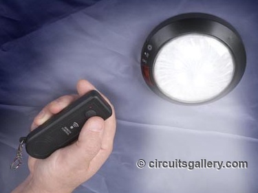
It is wonderful if you could control the light with your own remote controller circuit, isn’t it?
One of the best applications of 555 timers is used here, which is the Monostable multivibrator mode. If 555 IC is wired in Monostable multivibrator mode it will produce a square pulse whenever you apply a trigger to the 2nd pin with a low (1/3 Vcc) voltage.
In our remote controller circuit we have used a TSOP – IR Receiver module (costs around RS: 15/- only). It receives an IR signal from any remote controller (for the example TV remote, DVD player remote, etc.) and triggers the 555 IC.
Upon receiving this trigger 555 produces a square pulse that may give a clock to the next toggle Flip-Flop circuit. The output of toggle flip-flop is interconnected to relay circuit for interfacing electrical bulbs.
For the first clock, the flip-flop is set HIGH and remains there until it receives the next trigger from the remote. According to the flip flop output, the bulb turns ON and OFF.
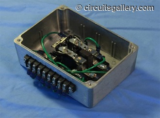
3. Automatic Water Tank Level Controller
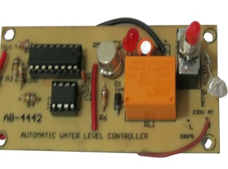
This is one of the most popular circuits and is especially suitable for Engineering mini-projects. It can automatically switch ON and OFF the domestic water pump set with respect to the tank water level.
The implementation task is too simple and this will work amazingly. The project consists of 3 wires, used to sense the current level of water inside the tank.
The heart of our circuit is a 555 timer. Here it is working neither as monostable nor astable, the configuration of the 555 is as a controllable flip flop which will set and reset back according to the correct inputs from the sensor probes. Output from 555 IC is fed to the relay driver transistor and the relay allows us to connect the electrical pump set.
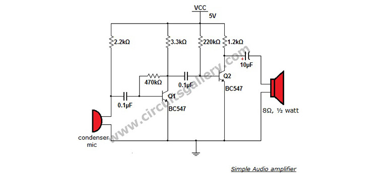
4. Clap Switch Circuit using 555 timer IC
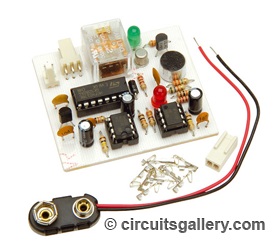
This circuit is almost similar to Remote Controlled lamp circuit, the only difference is it uses an Audio signal instead of an IR signal for triggering the 555 IC.
Here also the 555 is configured as a Monostable multivibrator, triggered by a simple amplifier. Any sound signal captured by the MIC is amplified and applied as trigger input of 555 timer IC.
After receiving this trigger 555 clocks the toggle flip flop and the output lamp section, interconnected to the flip flop via relay driver, thus the output bulb glows with respect to the state of the flip flop.
5. Burglar Alarm Circuit for Your Home Security
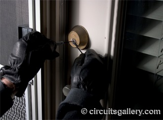
Home security systems are really expensive to implement and it is a complicated task. But electronics hobbyists may play with different security alarms and home security systems of their own. Here comes such a Burglar Alarm Circuit built around 555 timer IC.
This circuit utilizes the Monostable multivibrator mode of timer IC. Photo Diode and IR LED triggers the section.
IR rays continuously strike on the photodiode and once any obstacle crossed the rays, the circuit gets triggered, hence producing an alarm sound. Using the 555 timer circuits monostable calculator tool, you can calculate the duration of the sound.
The duration of the alarm influenced by a suitable selection of Resistor R1 and capacitor C1. This circuit is really secure since IR rays are invisible to human eyes.
6. Simple 555 Timer AM Transmitter Schematic for Science Fair Project
Amplitude Modulation (AM) is a popular method of modulating signals, actually in this way we are mixing a low-frequency signal to a high-frequency carrier wave.
In AM, the amplitude of the carrier wave is changed according to the amplitude of the message signal thereby increasing the energy of the message signal so that we can transmit to distant areas.
As we discussed earlier 555 IC generates high-frequency signals if it operates in Astable mode. External audio signal applied to this astable circuit and the amplitude of 555 pulses gets modulated due to the presence of an external audio signal.
Basically, the audio signal causes resetting of the IC, so no output at low amplitude levels and work normally at a high amplitude of message signal.
You can receive and hear the audio signal via conventional radio by tuning to the AM range.
7. 555 Touch Sensor or touch switch
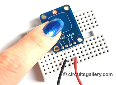
You might probably know that single touch ON/OFF circuits is widely used in different control systems and home automation.
For the 1st touch, the output load will perform its operation and for the next touch the load will shut down. The logic behind this control system is very simple and is easily achieved using 555 IC.
For the touch sensor circuit also 555 IC operates in Monostable mode. As the name indicates we need a “Touch Pate”, any metal plate can be served for this purpose.
Each touch is applied as a trigger input to the monostable multivibrator and the output of 555 is taken as a clock to the toggle flips flop as we explained earlier.
Each touch at the touch plate produces a single clock that will set and reset back the flip-flop. The output load is driven from the flip flop via a relay circuit.
8. 555 timer IC Inverter circuit
Here is the simple inverter circuit by 555 timer IC. The astable multivibrator mode operation of 555 timers is applied here.
The AC oscillations from the IC are switched via transistor 2SC4029 to a transformer. The transformer will step up the signal to high voltage AC.
This is a low-power inverter, that can handle up to 60 Watt while using a 10A transformer at the output.
9. PWM LED Dimmer/ Brightness Control by 555 Timer

How to adjust the brightness of LEDs? Most of us think that’s possible by varying current by a potentiometer! Is it practical?
It is not a proper way of adjusting the brightness of LEDs because LED is basically a diode, when the forward-biased voltage exceeds its cut in voltage the LED will glow.
By reducing the voltage or current we cannot vary the brightness of LEDs. So what’s the solution? Here we are presenting one efficient method for this issue.
It is based on the principle Pulse Width Modulation (PWM) such that the brightness of LED is proportional to the average value of square pulse from the PWM generator. Here 555 acts as a PWM generator and we can vary the pulse width by turning the pot.
10. Automatic Rain Sensing Wiper System using 555 Timer

Have you seen Audi, Lexus, or Ford rain-sensing wipers and doubted how they work in these vehicles?
The technology behind this is very simple to implement via a 555 timer. On these cars, there is a sensor in the middle of the glass. Of course, 555 IC works as a Monostable multivibrator here.
The sensor could be nearby arrangements of Ground wire and probe from trigger pin of 555. A small water drop triggers the Monostable and is followed by the activation of the relay circuit. The wiper motor is connected to the relay which in turn runs the wiper.
Conclusion
These are the top 555 Timer Projects Kits for Students. In this article, we tried to give an overview of the projects. As a result, you may initiate your work to fabricate a nice and fascinating project for your academic project or science fair. Also, you may realize the importance and unique features of 555 IC with a wide range of applications in science projects electronic circuits.
- 1. Electronic Mosquito, Insect Repellent Circuit Using 555 IC
- 2. Remote Control Light Circuit Diagram Using 555 Timer
- 3. Automatic Water Tank Level Controller
- 4. Clap Switch Circuit using 555 timer IC
- 5. Burglar Alarm Circuit for Your Home Security
- 6. Simple 555 Timer AM Transmitter Schematic for Science Fair Project
- 7. 555 Touch Sensor or touch switch
- 8. 555 timer IC Inverter circuit
- 9. PWM LED Dimmer/ Brightness Control by 555 Timer
- 10. Automatic Rain Sensing Wiper System using 555 Timer
- Conclusion
Subscribe to our newsletter
& plug into
the world of circuits
