Water Quality Checker Project | Simple Circuit Diagram
How to measure water purity? How to test water quality using a simple electronics project? You can perform water purity measurement and water quality analysis using this water quality checker project circuit.
This circuit is built around a simple LDR (Light Depended Resistor) and some discrete components. The detailed circuit diagram and constructional details of the water quality testing device are given in this article.
Also, you can integrate this with our previous circuit of water tank level controller, the resulting circuit will be an advanced engineering project.
When the amount of mud in the water reservoir exceeds a threshold value, our water quality testing equipment starts producing a beep sound to alert us that the quantity of mud in the water has increased and needs a cleaning.
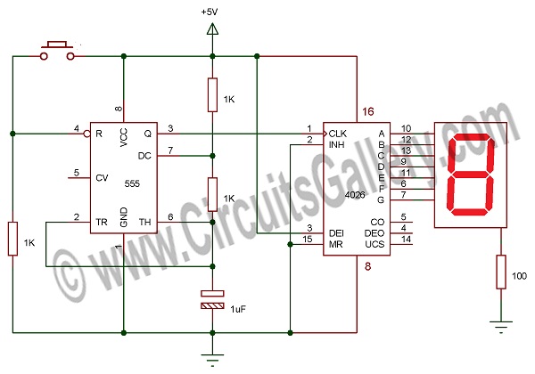
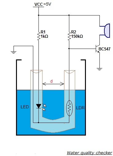
Circuit Diagram of Water Quality Checker Project
Components Required
- Power supply
- Resistors ¼ watt (1kΩ; 150kΩ)
- Light depended resistor (LDR)
- Transistor BC547
- Buzzer 6V
- Transparent flexible plastic tube
Working Principle of Water Quality Tester
- The main part of this tester is a LDR (Light Depended Resistor).
- The unique property of LDR is that it has very high resistance in the absence of light and very low resistance in the presence of light.
- We just connected a LDR and a resistor in a potential divider arrangement.
- Light from an LED is allowed to fall on the surface of LDR continuously. Hence the resistance offered by LDR is too small.
- If the resistance is too small the voltage drop across the LDR is also small (less than 0.6V) and it is insufficient to turn ON the transistor.
- When the amount of mud in the water tank increases, the water becomes dirty and the muddy water blocks the path of light rays from LED to LDR.
- This leads to resistance rise of LDR since small amount of light falls on the LDR.
- The increased resistance cause high voltage drop across the LDR and this high voltage leads to turning ON of the transistor.
- When the transistor becomes ON, current from Vcc starts flowing from Vcc to ground via the buzzer. Hence it produces beep sound.
- You can change the sensitivity of this circuit by adjusting the distance ‘d‘ marked in the circuit diagram.
- Insert the LED and LDR trough the flexible transparent plastic pipe as indicated in the circuit diagram.
Conclusion
The most attractive feature of our water quality checker project is that it gives a beep sound when the water purity level goes below a threshold value. You can implement this simple electronic project in your domestic water tank for water quality monitoring and testing.
Subscribe to our newsletter
& plug into
the world of circuits