2w Battery Powered Portable Audio Amplifier Circuit Using Tpa2025d1
Here we are dealing with a simple powered portable audio amplifier circuit using TPA2025D1 IC chip. The TPA2025D1 is a high-efficiency Class-D audio power amplifier (mini amp) with battery tracking AGC (Automatic Gain Control) technology.
We are also using an integrated Class-G boost converter that enhances efficiency at low output power. It drives up to 1.9 W into an 8Ω speaker (1% Total Harmonic Distortion- THD+N). With 85% typical efficiency, the TPA2025D1 helps extend battery life when playing audio.
The most important applications of TPA2025D1 IC are cell phones amplifiers, PDA, GPS, (microphone) headphone amplifier circuits, and portable electronics and speakers. You can construct this portable voice amplifier (mini power amp) at a cost of around $1.5 (USD).
Circuit Diagram of Simple Battery Powered Audio Amplifier
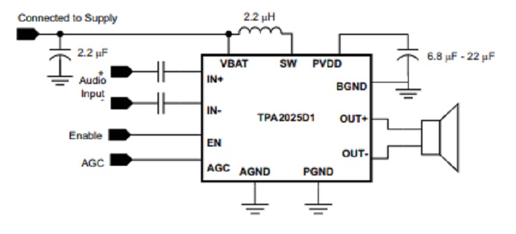
Components Required for Portable Audio Amplifier Circuit
- IC TPA2025D1
- Battery supply (1.5V x 3 Batteries)
- Capacitors (1µF x 2)
- Electrolytic capacitors (10µF, 16V; 2.2µF, 16V)
- Inductor (2.2µH)
- Microphone
- Speaker (1.9 W; 8Ω)
Working PRocedure of Powered Portable Audio Amplifier Circuit
- The working of this circuit can be easily explained by using the internal circuitry of IC TPA2025D1.
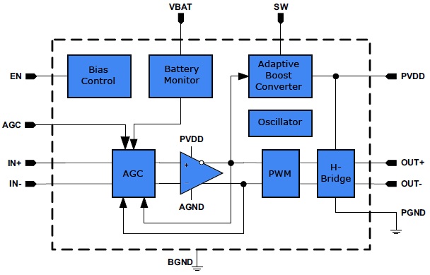
Internal block diagram of IC TPA2025D1
- Refer the internal block diagram; the 4.5V battery is connected to the battery monitor circuit, which monitors the battery power.
- The input audio signal is applied to the amplifier via AGC circuit, AGC stands for automatic gain control.
- The AGC circuit in the TPA2025D1 examines the battery voltage and automatically decreases the gain when the battery voltage is lower than a certain threshold voltage. This threshold value is termed as inflection point.
- Thus battery tracking AGC lowers the audio volume, it prevents high battery current at end of charge battery voltage.
- When the amplifier is switched ON, the gain is set with respect to battery voltage and selected inflection point (here we are using 10kΩ resistor to set inflection point).
The Boost Converter
- The TPA2025D1 consists of an integrated adaptive boost converter and a class D amplifier. The boost converter functions from the supply voltage and produces a high output voltage, which is connected to the output H bridge section and also to the amplifier section.
- This gives a louder audio output than an individual amplifier directly coupled to the battery. The battery tracking AGC regulates the class-D amplifier gain to limit battery current at lesser battery voltage.
The H-bridge
- H bridge section is driven by PWM circuitry, it produces PWM pulses related to the average values of input audio signal.
- To improve the signal to noise ratio (SNR) and RF rejection, TPA2025D1 has an inbuilt low pass filter.
The Auto Recovery Protection
- One of the main advantages of this IC is short circuit auto recovery protection. When a short circuit occurs, the TPA2025D1 operation changes to low duty cycle to protect the IC.
Conclusion
This proposed powered portable audio amplifier circuit is much dependent on the TPA2025D1 IC. Hence implementation of this particular amplifier asks for a sound understanding of the parts of the IC.
Subscribe to our newsletter
& plug into
the world of circuits