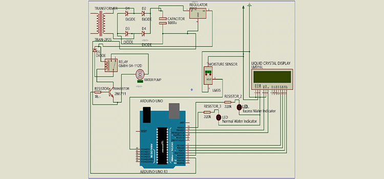
Introducing a smart irrigation system to your farm can increase your farming efficiency by saving water, energy, and manpower. It will support the sustainable growth of plants by supplying the right amount of water when required without any human intervention. Here we will present a demo model of such a system which can be scaled according to your requirements.
This advanced irrigation system uses soil moisture sensors for continuous monitoring of water content in the soil and will switch on the water pump if the moisture is less than a threshold level. The threshold value can be adjusted by turning the potentiometer attached to the sensor. The soil moisture sensor is the main part of the circuit which is easily available to buy locally as well as in online stores. This project uses no microcontrollers, in the near future we will come up with an IOT-based irrigation system, so stay tuned.
Circuit Diagram of Smart Irrigation system

Components Required
- Soil moisture Sensor
- BC548 Transistor
- Resistor (1K Ohm)
- Diode (1N4007 x2)
- Capacitor (1000uF/25V x1)
- Center Tapped Transformer (6-0-6/1A)
How does a soil moisture sensor work?
- The soil moisture sensor will sense the water content in the soil by measuring the resistance (water content in the soil will decrease the resistance).
- The sensor has two terminals that have to be dipped in soil. When powered, current will flow through the soil. If the soil has a low water content (dry soil), then the resistance will be high, and thus low current will flow through the soil.
- The current through soil is passed through a series of resistance (embedded within the sensor) connected to the ground which will make a voltage drop across it. This drop voltage is the sensing voltage which is then fed to a comparator IC to convert it to digital output.
- The compactor reference voltage is the threshold voltage and it can be varied by tuning the pot attached to the sensor.
- The moisture sensor has four pins VCC, GND, A0 (Analog), and D0 (Digital). D0 is connected to the base of a BC548 NPN transistor. As the basic electronics tells us, an NPN Transistor will switch ON when a positive voltage (greater than 0.6V) is applied to the base.
- So to summarize, when there is no water content in the soil, the sensor output will be positive, and hence base of the transistor will get a positive voltage through the 1K Ohm resistor and as a result, the transistor will switch ON. The 1K ohm resistor is used to limit the base current of the transistor.
- The positive terminal of the water pump is directly connected to the positive supply and the negative terminal is connected to the collector terminal of BC548. When the transistor is switched ON, the motor will get a negative voltage (GND) and it will be powered ON.
- If you want to connect a heavy motor then you have to connect a relay instead of the motor and then connect the AC motor at the output of the relay.
Conclusion
Many farmers have suffered from poor management of irrigation. This project will solve their biggest problem of them and will ensure maximum production at a lower cost.
Leave a Reply