Low Pass Filter | Integrator Circuit Using Op Amp 741
Here we are opening the door to a very wide range of useful and exciting applications of the opamp. Here we are discussing an opamp RC circuit named as opamp integrator circuit. This circuit simply performs the integration of the input waveform.
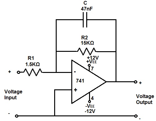
Circuit Diagram of Low Pass Filter
Components Required
- Resistors (10kΩ, 15kΩ)
- Capacitor (0.01µF x 2)
- Op-amp 741 x 1
Working on Integrator Circuit
- The gain and linearity of the waveform are two important advantages of opamp integrators over ordinary RC integrators.
- Linearity of the waveform is achieved by the constant current through the capacitor.
- Due to the property of virtual ground, the current through the input resistor (R1) is constant owing to the constant potential drop across it.
- Current through the input resistor and capacitor is the same due to the high input impedance of Op-Amp.
- At low frequencies of the input voltage, the capacitor behaves as an open circuit.
- Op-Amp may saturate at low frequency even for a very low input voltage. This is because the open loop gain is very high.
- Here we use a very high-value feedback resistor Rf to prevent the opamp from saturation.
- When Rf is connected, the gain will be reduced considerably at low frequencies.
- At higher frequencies circuit behaves as an ordinary integrator.
- Simply the fact is that at low frequencies, Rf is effective and C is effective at high frequencies in the feedback path.
- If we are feeding a square waveform to the input of the Integrator, the output will be a Triangular wave.
Design
Take input frequency = 1KHz
We know the relation, f = 1/(2πRC)
For Convenience let C = 0.01µF. Then R = 15KΩ
Select high value for Rf such that Rf = 10R Ie; Rf = 150KΩ
Conclusion
Opamp integrators are commonly used in analog computers and wave shaping networks. Integrator is also known as first order low pass filter. It permits low frequencies to pass to the output.
Subscribe to our newsletter
& plug into
the world of circuits
I completely agree with the article that opamp integrator circuits are incredibly useful and versatile in many different applications. The ability to achieve linearity of the waveform through constant current and virtual ground is a significant advantage over ordinary RC integrators. I also appreciate the emphasis on the importance of choosing appropriate values for the resistors and capacitors in the design process to achieve the desired output. Overall, this article does an excellent job of explaining the concepts and practical considerations involved in designing and using opamp integrator circuits.
Thank you for sharing your thoughts!
Thank you for the clear explanation. previously I was confused about difference of integrator and first order LPF circuit
Thank you for your comment. Stay with us for clarifications on any topics.