Laser Communication Project Circuit Schematic Using Laser Diode and lm386 Low Voltage Audio Amplifier
Laser communication project circuit is a popular basic project that is a useful part of many big projects. The LM386 is a low voltage power amplifier (audio amp chip) IC. This circuit is usful in low voltage customer applications. The inside gain is set to 20, but adding an external resistor and capacitor between pins 1 and 8, will enlarge the gain to any value from 20 to 200. The inputs are ground referenced while the output automatically biases to one-half the supply voltage. The quiescent power drain is only 36 milliwatts when operating from a 9 volt supply. Here is a laser communication transmitter and LASER communication receiver circuit schematic.

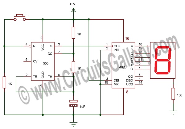
Circuit Diagram of Laser Communication Transmitter
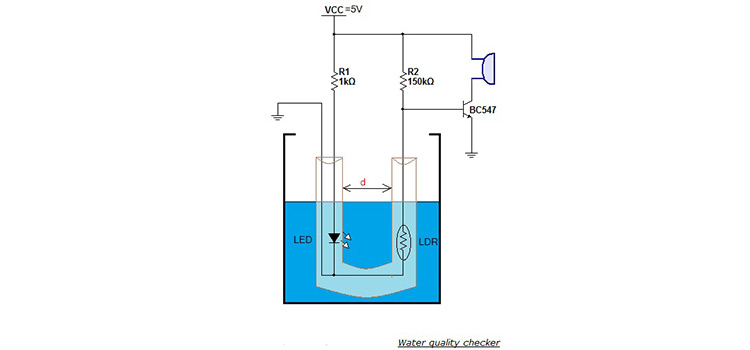
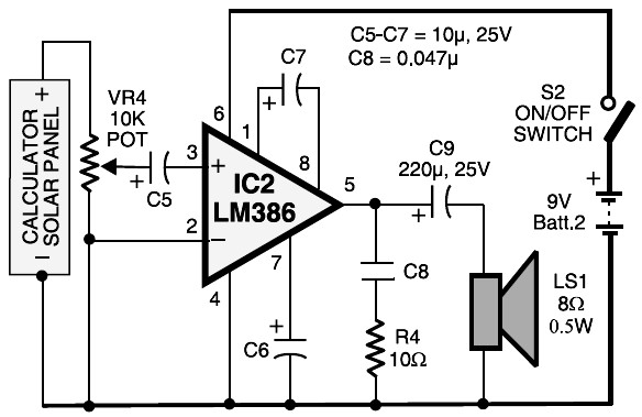
Circuit Diagram of Laser Communication Receiver
Components Required for Laser Communication Project Circuit
- LM386 IC x 2
- Potentio meters (VR1=10k Ω, VR4=10k Ω)
- Presets (VR2=220 Ω)
- Resistors (10Ω x 2, 56 Ω x 2)
- Capacitors (100µF-25V, 10µF-25V x 5, 0.047µF x 2, 220µF-25V)
- Calculator’s solar panel
- Laser diode
- Speaker (8 Ω, 0.5W)
Working Laser Communication Transmitter
- This laser communication system transmits sounds though a laser beam. The intensity of laser beam changes with the amplitude of sound signal.
- The variation in LASER beam intensity is converted to variation in voltage level by using a calculator’s solar panel.
- The voltage variation in solar panel is amplified by a low voltage audio power amplifier LM386 and reproduced by speaker.
- The maximum output of audio amplifier LM386 is 1 watt, while its voltage gain is 20 t0 200.
- Here laser diode with maximum operating voltage 2.6 Volt and maximum operating current 45mA is to transmit the audio signal.
- The voltage divider formed by R2, R3, VR3 keep the voltage as well as the current for the laser diode. Potentio meter VR1 changes the level of the input audio signal. Apply input audio signal from mic, CD player or any other device.
- Capacitor C2 and preset VR2 vary the gain of audio power amplifier LM386 IC.
Working Laser Communication Receiver
- The transmitted light is received by calculator’s solar panel and amplified by audio power amplifier LM386.
- capacitor C7 fixes the gain of the amplifier.
- Preset VR4 changes the signal level from solar panel.
- C5 acts as coupling capacitor it removes the DC voltages from the solar panel.
- The output is fed to speaker via another coupling capacitor C8
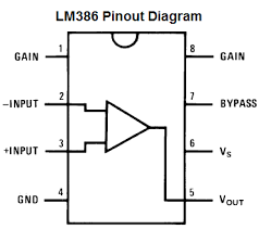
Pin Out of lm386 and Other Components
LM386
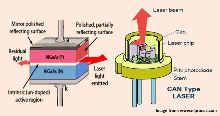
LASER Diode
Conclusion
In this article, we have briefly described the schematic and working principle of laser Communication project circuit. Here we use a simple lm386 IC and a laser diode. This is a simple project and anyone can fabricate it within a short period of time.
Subscribe to our newsletter
& plug into
the world of circuits