Project for Electronics and Communication | Automatic Road Sign Detection, Recognition, and Command System
At colleges, it’s a busy time now as I can see a lot of my friends running around to get their engineering major projects approved (Luckily mine got approved ?). Here at circuitsgallery.com we already have a fine collection of mini-projects on electronics and communication. You can browse them to see if any of them suits your requirements.
So on this occasion, I would like to present you with good microcontroller-based final year projects. If your confidence level is good enough, then I bet you can easily do this project for electronics and communication by yourself.
This system is designed to detect signboards on the road and give out the related audio commands. Moreover, it displays the information on the display connected to the system. Also with the application of additional systems, the speed of the vehicles can be controlled automatically.
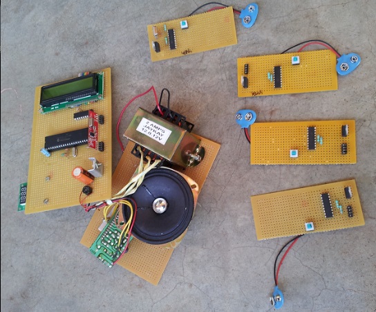
The main part of this system is a PIC Microcontroller (PIC16F877A), which controls the overall operations of the system. An LCD display is used to display information about the driving area, an MP3 player is used to command the signals, and RF transmitters are used for the detection of signboards.
It can be implemented in any vehicle as it reduces the inattention of the drivers and ensures safe driving.
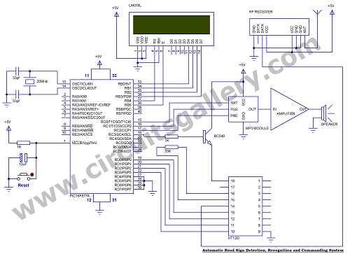
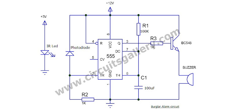
Circuit Diagram of Automatic Road Sign Detection System
Components Required
- PIC16F877A
- LCD Display (2×16)
- MP3 player module
- Amplifier board
- RF Transmitter and Receiver
- IC HT12E
- IC HT12D
- IC 7805×5 (Depend on the no of signs used)
- Transistor BC548
- Bridge IC
- Crystal (20MHz)
- Capacitor(1uF/16V,33pfx2,1000uF/25V)
- Resistor(33K,750K,1K,x2)
- 9V Battery connecter x4
- Doted PCB Boards
- Speaker
- Transformer 0-12V/1A
- 9V Batteriesx4
- USB socket (available with MP3 module)
- ON/OFF switches
- Power code wire
Working Principle of the Road Sign Recognition and Command System
- Each of the signboards requires an RF Transmitter which sends RF signals continuously.
- Along with the RF Transmitter, a serial encoder IC HT12E is used, which sends a particular data depending on its data input.
- An RF Receiver is fitted onto the vehicle to receive signals from the signboard and the serial decoder IC HT12D connected to it decodes the signboard data.
- The received data is identified and interpreted by the microcontroller which selects the particular command for that signboard.
- Commands may be stored on pen drives or memory cards connected to the MP3 player. PIC Microcontroller selects the command with the help of an MP3 player. The commands stored should be in supported format (MP3).
- The first mp3 command should be blank (no sound) and each one should be numbered as 1,2,3…..etc. The numbering helps to select particular commands by the microcontroller.
- For the command selection, 3 signals are mainly used- “Previous”, “Pause” and “Next”.
- PIC is connected with an MP3 player with these signals, for that, we use PORTC.0, PORTC.1, and PORTC.2( PORTC.0 means the first bit of PORTC).
- PORTC.3 is also used here to reset the decoder IC HT12D, which has no built-in reset pin we use a transistor BC 548 to switch its power to reset the IC.
- Let’s suppose the vehicle is moving, when it reaches next a (50 meters) signboard the receiver in the vehicle receives the RF signal, then the decoder decodes the corresponding signboard signal and is fed to the microcontroller. Microcontrollers then check the data, send data to LCD for displaying and also select the command corresponding to the signboard. The command selection is done by using the three signals as explained above.
Command Selection
- The microcontroller identifies the command required for a particular signboard.
- When the system is switched ON after 5 seconds microcontroller will pause the first command (blank).
- After identification, it sends the signal “next” to the MP3 player to select the particular command. It sends two clocks for each command selection.
- After selection it waits 5 seconds to play the command, then sends the “previous” signal to select the first command and it’s again paused with the “Pause” command.
- The number of clocks required for each command depends on the name stored in the pen drive or SD card.
Amplification
- An amplifier and speaker system are used to amplify the voice output from the MP3 player.
- Mp3 player has three analog outputs: right, left, and analog ground.
- We require only analog ground and any one of right or left, which is connected to the amplifier.
- Any suitable speaker can be connected to the amplifier to get the voice output.
Transmitter
- The number of transmitters depends on the number of signboards.
- While connected to the signboard, it can be powered by a battery on any other source like solar.
- Here we use widely available RF transmitters and receivers whose range is about 50 meters, so the vehicle receiver commands when it reaches around 50 meters.
Display
- A 2×16 LCD display is used here to display the command corresponding to a particular signboard.
- The display is controlled by the microcontroller, it’s set to show “Drive care” when the receiver is at rest.
In this project, use the Mikro C compiler.
Conclusion
I hope this project was useful to someone. In the future, we’ll be coming up with a more interesting list of major projects for electronics and communication. You can also send your projects to use as it may help someone. All the best for your projects!
Subscribe to our newsletter
& plug into
the world of circuits

