Heartbeat Monitor Project Circuit with Tachycardia Alarm
The present Medical Electronics deals with many technologies like ECG (Electro Cardio Gram), EEG (Electro Encephalo Gram), Cardiac monitors, etc. Almost all multispecialty hospitals equipped with modern technologies are coming from Electronics.
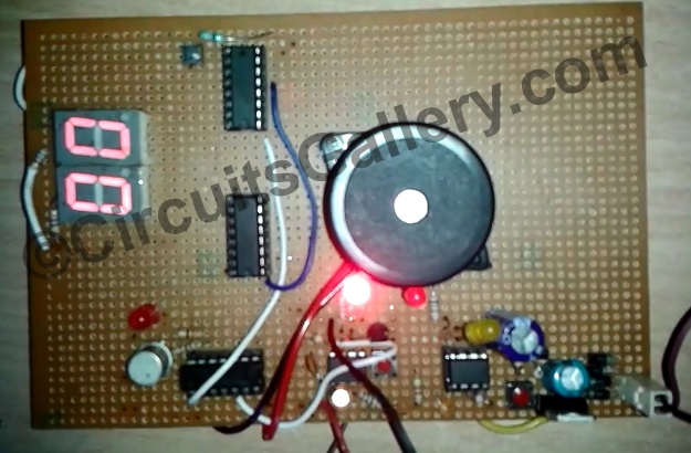
Let me introduce here a heartbeat monitor project that can monitor the heartbeat and displays in a seven-segment display. Moreover, it makes an alarm if the heart pulse is greater than 80 pulses per minute.
The main part of the heart rate monitor final year project is 4026 IC it has an inbuilt counter and seven-segment driver embedded in a single IC. It is used to count the pulse from the sensor. Then two mono stables multivibrators are utilized, one to enable counting for 1 minute and another for feeding pulses from the heartbeat sensor circuitry.
Many Engineering and Diploma students did mini projects on heart rate monitors. You can also develop a project report on heart rate monitor with this article.
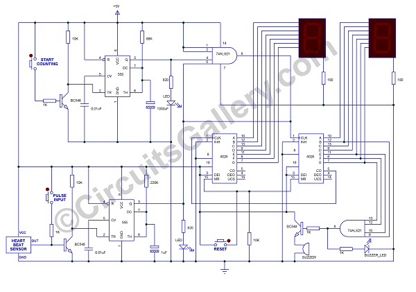
Heart Rate Monitor Project Circuit Diagram
Components Required for Digital Heartbeat Monitor Project Circuit
- IC 4026 x 2
- IC 74LS21
- IC 555 x2
- Transistor (BC548x3)
- Resistor (1Kx4, 10Kx3, 68K, 220K, 820×2, 100×2)
- Capacitor (1000µF/16V, 1µF/16V, 0.01µF x 2)
- Seven segment display x2 (common cathode)
- LED x3
- Push-button x3
- Buzzer (5V)
- Heartbeat sensor
Working Principle of Heart Beat Monitor Circuit
Now let’s discuss the working principle of the heartbeat monitoring system project
- The 1st part is the Heart Beat Sensor module, It is available in common electronics shops. A heartbeat sensor is an embedded package module having 3 terminals Vcc, Ground, and Out.
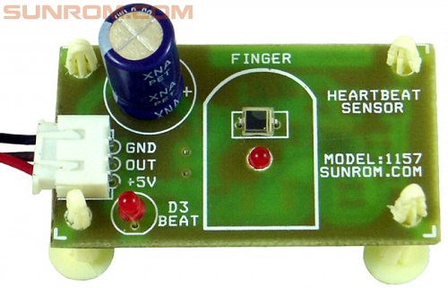
- It senses the heart rate once you hold the sensing area with your finger and produces small electrical signal output with respect to the Heart rate. These signals are manipulated and amplified by our circuit.
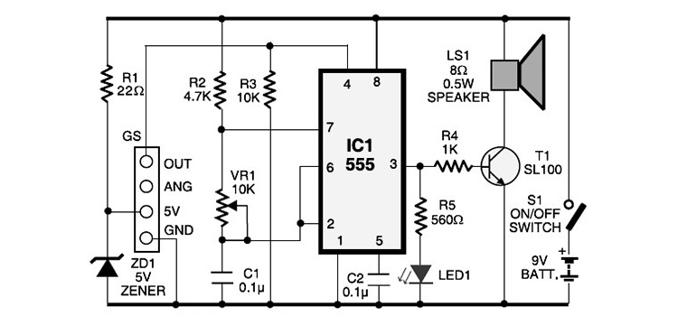
- A monostable using a 555 timer is designed for 1 minute which is used to enable the clock to the counter for one minute.
- Another monostable circuit is intended for giving a perfect clock to the counter which helps to remove the noise effect.
- IC 74LS21 is a four-input AND gate IC used to connect the clock to the counter IC after getting the enable signals, also it helps to enable the buzzer when the count reaches 80.
- AND gate will enable the clock for one minute with the help of a monostable (designed for 1 minute).
- When the push button (start count) is pressed, then the monostable output is high for one minute and the counter starts counting if the heartbeat sensor is connected.
- After one-minute monostable OFF and thus clock will disable by AND gate and reading can be taken from the seven-segment display.
- If the number of pulses is greater than 80 then AND gate output gets in to high.
- The output of AND gate is fed to the transistor through a 1K resistor, so the transistor turns ON the buzzer and produces an alarm sound.
- 2nd AND gate is used to check whether the count value is greater than 80, the process is achieved by connecting the outputs (6, 7, 11, 12) of 4026 to the four inputs AND gate, AND output will high only when the counter output is 80.
- IC 74LS21 is sensitive to the input supply voltage. The maximum rating of this IC is +5V, so please use a voltage regulator circuit using 7805 IC.
Conclusion
The heart rate monitors electronic project useful for you for the Mini-project of the final year project. Some genius school students can do a heart rate monitor science fair projects with the circuit.
Subscribe to our newsletter
& plug into
the world of circuits


