Voltage Control Circuits | Regulator, Stabilizer, and Protection
Voltage fluctuation is a serious issue in every home and office. Due to a bunch of reasons, the supply voltage may rise above 110V or 230V. The flow of this high electricity may damage your home electrical devices. You can easily solve this problem using voltage control circuits such as voltage regulators, voltage stabilizers, and voltage protection circuits.
Although voltage regulators and stabilizers can be found on the market, if you can make one at your home, it would save a lot of costs.
In this article, we are going to show how you can make –
- A voltage regulator using some cheap and effective alternative components,
- A simple over-voltage protection circuit that will protect your electrical appliances from high voltage,
- An AC voltage stabilizer that will alert you whenever the voltage goes below the preset level.
The advantages of these circuits are that you can use resistors instead of transformers to control voltage, which reduces the cost for these circuits. You can also use these circuits for your school projects too.
So, don’t waste any more of your valuable time looking for other voltage-controlling projects online. Read by the end of this article to make your own voltage-control circuit using some simple methods.
1. Voltage Regulator Using Zener Diode Circuit
This simple circuit only requires a Zener diode and a passive electronic element- resistor. The Zener diode works as a regulator and is used in any small or big-scale project to regulate the voltage of any point inside the circuit. This regulated voltage output is essential for the circuit to control the voltage of any point.
This circuit is handy for obtaining a regulated voltage at the output. As a result, you can use it in any circuit for biasing other circuit elements. When Zener diode is in the reverse breakdown region, the voltage across it remains almost constant irrespective of the current through it.
The major benefit of making a voltage regulator using Zener diode circuit is that it helps us to avoid the bulky & costly DC source to a great extent. Follow the schematics and diagrams below and make the Voltage Regulator using Zener Diode Circuit.
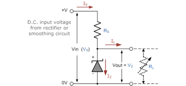
Zener as Voltage Regulator Circuit Diagram
Components Required
- Resistors (100Ω)
- Potentiometer (1KΩ)
- Zener diode
Working of Zener Voltage regulator
- A Zener diode functions as an ordinary diode when it is forward-biased. This specially designed device is for operating in the reverse bias condition.
- The 100Ω resistance limits the current through zener diode beyond its maximum limit.
- Meanwhile, when the input voltage increases, IL remains the same (load current). Is (current through the series resistor) and Iz (Zener current) increases.
- If input voltage decreases, IL remains the same. Iz & Is decreases. If Iz falls lower than the minimum Zener current required to keep the Zener in the breakdown region, the regulation will stop and voltage at the output will decrease.
The success of any electronic project depends on how well-defined the voltage of every point is. A Zener diode circuit is the best option to design a compact and powerful voltage regulator.
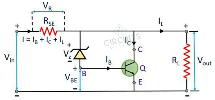
2. Simple Overvoltage Protection Circuit | High Voltage Cut Off
Here is described an interesting overvoltage protection circuit to protect your electrical appliances from high voltage. The Zener diode voltage regulator is the main part of this high-voltage cut-off circuit. You can implement this over-voltage protection relay circuit as a high-voltage regulator in your home. Let’s start making the circuit below.
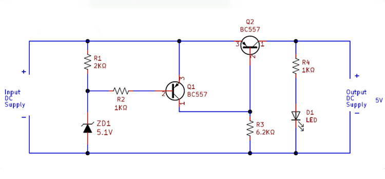
Circuit Diagram of Over Voltage Protection Circuit
Components Required for High Voltage Cut-Off Circuit
- Transformer (110V to 12V or 230V to 12V)
- Diodes (1N4007 x 5)
- Zener diode (6.2V)
- Capacitor (1000µF, 25V)
- Resistors (5.6kΩ; 6.8kΩ; 1kΩ)
- Potentio meter (10kΩ)
- Transistors (BC187 x 2; BC547)
- 12V relay
Working principle of the Surge Protection Circuit
- R1 and R2 forms a potential divider network, we can adjust the cut-off voltage by varying the 10K pot (R2).
- The neutral line is directly connected to the ‘Common’ terminal of the relay, then the ‘NO’ terminal and Phase lines are fed to the home appliances.
- Q3 is always in an ON state, so the relay connects the electrical appliances to the mains.
- At normal conditions, a small amount of current will flow through the Zener diode, but it is insufficient to turn ON the transistor Q1.
- A sudden increase in supply voltage (over-voltage) leads to the rise of Zener current. This current will turn ON the transistor Q1.
- The collector voltage of Q1 is applied to the base of Q2. Thus, Q2 and Q3 become OFF because the transistor acts as a digital switch here.
- Q3 is our relay driver, turning OFF of Q3 shuts down the relay too. When the relay is OFF, there will be no supply of electricity to the device. Hence, they protected from overvoltage.
Voltage surge is a common problem for almost all electronic devices and this over-voltage protection circuit of ours can equip electrical devices to be resistant to such voltage surges.
3. AC Voltage Stabilizer Circuit Diagram | with Low Voltage Alarm
Due to the fluctuation of supply voltage your electronic devices may malfunction or damage permanently. To avoid these problems you’ll need an AC voltage stabilizer. Here we are going to introduce a simple voltage stabilizer circuit diagram for low-current devices.
The main advantage of this voltage regulator is that it will not use any kind of transformer in the circuit. Then how stabilizing is possible?
Well, we all know that the resistor circuit can do stabilizing. This voltage stabilizer circuit for AC uses only a resistor to reduce the voltage.
Moreover, the circuit is embedded with a buzzer that will alert you when the supply voltage turns below a preset level. Follow the instructions below and build a home voltage stabilizer of your own.
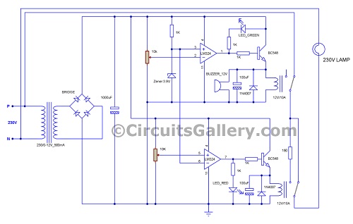
Voltage Stabilizer Circuit Diagram
Components Required for Voltage Stabilizer
- IC LM324
- Transistor (BC548x2)
- Zener diode (3.9V)
- Bridge
- Diode (1N4007x2)
- LED (Green, Red)
- Capacitor (100uFx2, 1000uF)
- Resistor (1Kx5,180/20 watts)
- POT (10Kx2)
- Buzzer (12V)
- Relay (12V/10A)
- Transformer (230V/0-12V; 500mA)
- 15-watt incandescent lamp
Working Principle of a Voltage Stabilizer Circuit
- The circuit design of the stabilizer is quite easy and compact. This is a relay-type voltage stabilizer circuit diagram.
- A 12V step-down transformer is used to drive the stabilizer circuit and the same transformer is used to analyze the input line voltage.
- A bridge rectifier is employed to convert AC to DC and a 1000µF capacitor is used to filter AC ripples.
- LM342 has four embedded comparators, among those we have used only two comparators for our stabilizer. The first comparator compares low voltage levels and another one for comparing high voltage levels.
- A 3.9V Zener diode is used to obtain a reference voltage of 3.9V (can use any Zener diode of below 6V) and this reference voltage is used by both comparators.
- The reference voltage is connected to the non-inverting terminal of the upper comparator and the potentiometer is connected to inverting terminal. Then adjust the potentiometer value to get a voltage greater than 3.9V (reference voltage) by keeping the normal input voltage.
- Inverting terminal of the lower comparator is connected to the reference voltage and the potentiometer corresponding to it is set to a voltage that is below the reference voltage (3.9 V) at the non-inverting terminal.
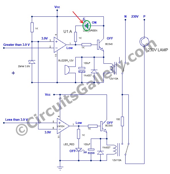
Case 1: Normal Supply Voltage
- In this situation, both comparators are OFF (Output is low).
- At normal supply voltage, the lamp appears to be directly connected between phase and neutral. Same time the output of upper comparator is negative then LED_GREEN is ON, which indicates that the input is normal.
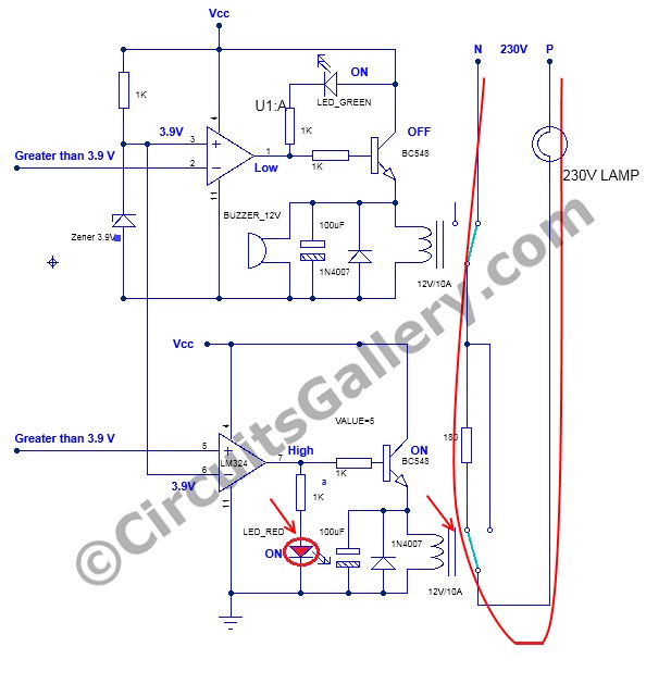
Case 2: Supply Voltage Increases
- When the AC input voltage is increased, the corresponding output of DC also increases. But, when it exceeds preset level 3.9 V, obviously the voltage drop across both potentiometers will increase. Again, as the voltage drop becomes greater than 3.9V, the output of the lower comparator will become positive.
- It leads to LED_RED and transistor to become ON, thus relay will switch and the connection to the lamp becomes through the resistor. So the voltage drop across the lamp will reduce since the resistor and lamp will come in series to the main supply. (LED_RED indicates the supply voltage increased).
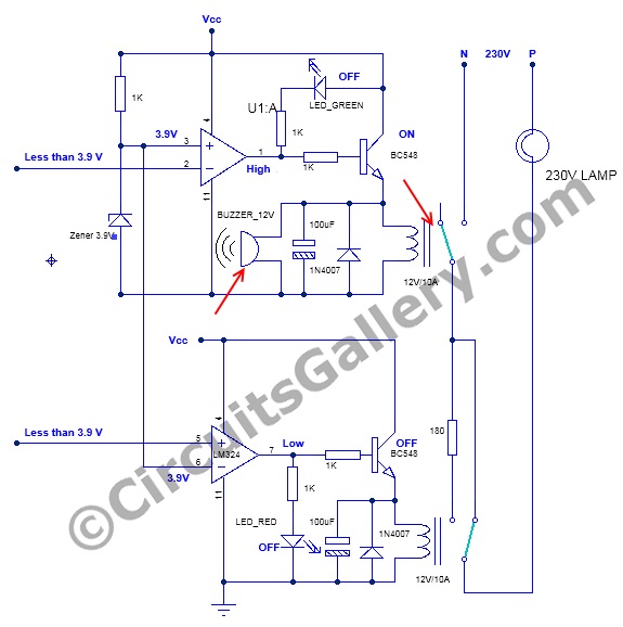
Case 3: Supply Voltage Decreases (Approximately Below 180v AC)
- When the line voltage is below a threshold level then the voltage drop across both potentiometers will decrease, then the non-inverting terminal of the upper comparator gets higher voltage than inverting terminal.
- Then the output of the upper comparator becomes positive and LED_GREEN turns OFF.
- Transistor gets turned ON, accordingly relay ON which make disconnection of the lamp from the supply. Same time buzzer is also turned ON to indicate the line voltage is below 180 volts.
In this way, our stabilizer controls the output load.
- The value of the series resistor connected to the lamp depends on the load power, for high power devices higher wattage resistors should be used.
- We can build a high power stabilizer by little alteration in the circuit together with a step-up transformer which can be used for refrigerators, TV, washing machines, etc.
This low-cost voltage stabilizer circuit diagram reflects that the regulator is controlled by a simple comparator IC LM324. It makes the circuit more effective for stabilizing the AC voltages.
Conclusion
There are very few appliances that can withstand voltages higher than rated. Voltage regulation is mandatory for keeping your electronic devices safe. Now, is it reasonable to buy an expensive voltage stabilizer from the local market when you can make a better one at your home? A home-built budget-friendly solution is always better for the protection of your appliances. We have provided a complete guide on making a voltage control circuit using some effective and budget-friendly components in this article, and we hope, you’ve found this guide very helpful in saving your home appliances. Go ahead and make one by following the above instructions.
Subscribe to our newsletter
& plug into
the world of circuits
Yes
Thanks for your feedback. If you have any further questions, feel free to ask!