What Gauge Wire for 1000 Watt Amp | 4 Effective Methods
The suggested wire gauge for a 1000-watt amp is a 4-gauge wire. This is because a 4-gauge wire has a current carrying capacity of up to 100 amps, which corresponds to the average current consumption of a 1000-watt amp. Smaller wire gauges, such as 8-gauge or 10-gauge, might be unable to manage the amp’s current draw without melting or overheating.
The precise wire gauge you require will depend on the particular amp you’re using, the distance the wire must travel, and the surrounding temperature. In general, larger wires are required for longer wire runs to decrease voltage drop and assure effective power transmission. In the following sections, the specifics are covered.
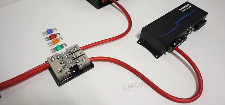
Considerations for Choosing Gauge Wire for 1000 Watt Amp
Typical advice is to use a 4-gauge wire for a 1000 Watt amplifier. The balance of ampacity, voltage drop, and safety margin is provided by this gauge. The 8.3 amps (1000 Watts at 120V) required for the amp are significantly beyond the 70 amps that the 4-gauge wire is made to carry.
This decision takes into account potential future power demands, lowering the risk of voltage drop and reducing the likelihood that the wire will get too hot. Some factors behind choosing this gauge wire are given below.
1. Current Handling Capacity
A wire gauge that can manage the power requirement of a 1000 Watt amplifier without overheating or creating voltage drop is necessary. As mentioned earlier, a 4-gauge wire may support current flows of up to 100 amps. Smaller wire gauges, such as 8-gauge or 10-gauge, may present a risk.
2. Resistance
As the length of a wire rises, so does its resistance. For the same amount of current to be carried without melting or overheating, a longer wire will therefore need to be a thicker gauge. In comparison to a 1000-watt amp with a 5-foot wire run, a 1000-watt amp with a 10-foot wire run requires a bigger wire gauge.
A 1000-watt amp run over 15 feet can still be completed with a 4-gauge wire. This is because a wire’s resistance rises as its length rises, but not linearly. A 15-foot run will just slightly increase the cable’s resistance, allowing a 4-gauge wire to deliver the current without overheating or melting.
3. Quality
Better insulation and a lower risk of melting characterize higher-quality wire. This is critical for power wires, which handle large currents and may become warm. A 4-gauge wire from a well-known manufacturer will be constructed from high-quality components and be less likely to malfunction than a 4-gauge wire from a less well-known manufacturer.
4. Environmental Attribute
When selecting a wire gauge, it’s crucial to take these things into account in addition to the ambient temperature. It is better to use a thicker gauge of wire if you reside in a hot region as opposed to a cold one. This is due to the wire needing to be able to manage the higher current draw as a result of the wire heating up more in hot weather.
For a Shorter Wire Run, May I Use a Thinner Wire Gauge?
Even though shorter wire lines have less voltage drop, 4-gauge wire is still suggested for a 1000 Watt amp. This offers a margin of safety and gets ready for any future power requirements or system modifications.
Conclusion
To ensure optimum performance, safety, and efficiency, choosing the proper wire gauge is essential. A compromise between ampacity, voltage drop considerations, and the opportunity for future system improvements can be found with a 4 gauge wire in the case of 1000 watt amp. Ultimately, speaking with an experienced installer is always recommended.
Subscribe to our newsletter
& plug into
the world of circuits
![Can I Use 10 Gauge Wire on a 20 Amp Circuit [Answered with Mathematical References]](https://www.circuitsgallery.com/wp-content/uploads/2023/06/Can-I-Use-10-Gauge-Wire-on-a-20-Amp-Circuit.webp)
