What Gauge Wire for Trailer Brakes? – Understanding Wire Gauge Requirements for Trailer Brakes
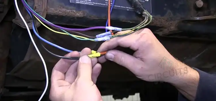
Trailer breaks generally employ wires between 14 and 10 AWG in size. The smallest size required to power a typical trailer brake is 14 AWG. To guarantee that enough power is given to the brakes, it is advisable to use 12 to 10 AWG ones for larger trailers.
The maximum current draw of the brake system determines the gauge of wire needed for trailer brakes. The greater the current draw, the thicker the wire gauge required for safe and effective operation. It’s important to adhere to local laws and safety standards when installing trailer brakes and wiring.
Wire Gauge Selection for Efficient Trailer Brakes
The common diameters for trailer brakes range from 14 to 10 American wire gauge (AWG). Remember that choosing a small wire gauge can cause high voltage drops, insufficient power, and possible safety hazards. However, an overly thick wire gauge can be expensive and may not offer any further advantages.
Although they don’t always need the same amount of electricity, trailer electronic brakes are power-hungry devices that need a sizable, reliable power source. How much power your trailer brakes require will determine the gauge wire size in major parts. Assume that the wiring line is 25 feet long and the maximum power draw for the trailer brake system is 15 amps.
According to the National Electrical Code (NEC), the permissible voltage drop is 3% of the nominal voltage. If the nominal voltage is say 12V,
maximum voltage drop = 0.03 * 12V= 0.36V.
Maximum resistance = Maximum voltage drop / Maximum current draw
= 0.36V / 15A
= 0.024 ohms
Compatible Wire Gauge for Trailer Brakes
The smallest size required to power a typical trailer brake is 14 AWG. It can also consistently supply that power at around 30 degrees. A table meeting NEC specifications about wire gauges for trailer brakes is given below.
| Wire Gauge | Amps | Trailer Size | Compatible Components |
| 14 AWG | 20 | Small (1-2 axles) | Standard electric brakes |
| 12 AWG | 25 | Medium (3-4 axles) | Larger electric brakes |
| 10 AWG | 30 | Large (5+ axles) | Heavy-duty electric brakes |
Can I Use 12 Gauge Wire for Trailer Brakes?
Yes, you can. However, it’s crucial to take into account the precise specifications of your trailer brake system as well as the maximum current draw it can generate. The typical current carrying capacity of 12-gauge wire is about 25 amps.
Using a 12-gauge wire should be adequate if the maximum current draw of your trailer brake system is within this range. If your brake system has a higher current demand such as 30 or more amps, and longer wiring length, it is safer to go for 10-gauge or even 8-gauge.
We know, resistance = ρ x L / A where the resistivity (ρ) is constant. The more the wire diameter, the lesser the resistance. For the same current, it results in a reduced voltage drop. Since, the lower the gauge, the bigger the diameter, for a longer run lower gauge is preferable.
Does Accurate Wiring for Trailer Brakes Matter?
Yes, it does matter. To ensure the braking system operates safely and effectively, the wire used for trailer brakes is essential. The following are the factors that influence wire selection.
Current Handling Capacity
The maximum current draw of the brake system must be accommodated by the wire used for trailer brakes. For example, as mentioned in the given table, 14 gauge is suitable for 20 amps. If the current of the trailer brake is more than 20 amps, it may result in an electrical hazard if a 14 gauge is used.
Voltage Drop
Voltage drop can be caused by longer wiring runs between the brake controller and the trailer brakes. The permissible voltage drop is as mentioned 3% by NEC.
Voltage drop (Vd) = Current (I) x Resistance per foot (r) x Length (L)
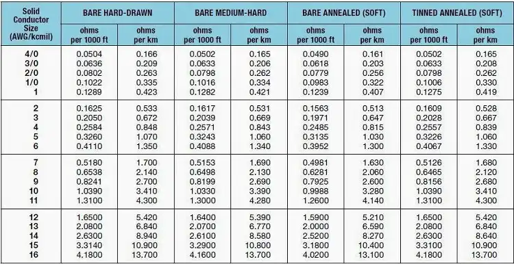
Assume we have a 50-foot-long, 14-gauge wire with a 10-amp current flowing through it. Now, 50 feet is equivalent to 50/1000 = 0.05 units of 1000 feet.
Vd = 10 A * (2.525 ohms/1000 ft) * 0.05 ft
Vd ≈ 0.0126 volts or 12.6 millivolts
You can use any online voltage calculator to do the maths as well. Here’s a link for your convenience.
Final Words
Just like the right tool for the job, the right wire gauge enables the brakes to perform their stopping power dance flawlessly. If you’re certain about the brake’s power requirement, choose the gauge wire best suited for its power requirements. Otherwise, you can be cautious and use a heavy-duty trailer wire like the 10 AWG to guarantee the brake’s functionality.
Subscribe to our newsletter
& plug into
the world of circuits