Emerson Electric Motors Wiring Diagram | Learn Ins & Outs of the Diagram
An electric motor is an electrical device that transforms electrical energy into mechanical energy.
Ferguson, Missouri serves as the corporate headquarters for the American multinational Emerson Electric Co. The company manufactures products and provides engineering services for industrial, commercial, and consumer markets.
According to their company name, these motors are named Emerson electric motors.
Braking Down the Wiring Diagram of Emerson Electric Motors
What Are the 3 Wires on an Electric Motor?
The lead wire colors for a common 3-wire motor are generally white, red, and black. Neutral is always associated with black (N). Black and white are both linked to the two terminals of the specific capacitor.
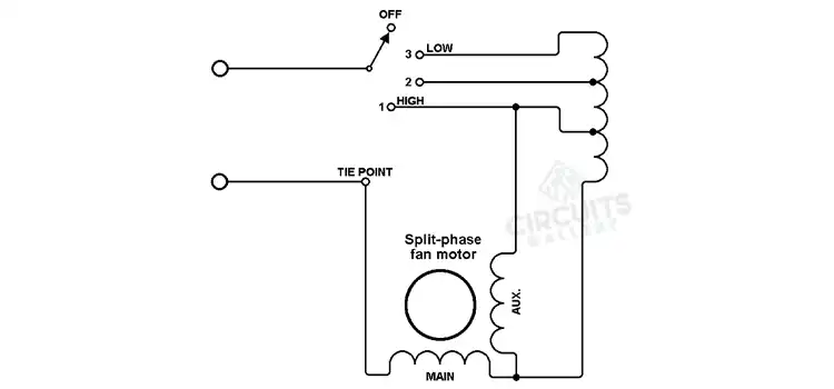
How Do You Wire a Single-Phase Electric Motor?
A single-phase motor cannot start on its own. Because of this, the process uses two windings: the starting winding and the running winding.
While the running winding is used to rotate the motor continuously, the starting winding is utilized to start or supply initial torque to the motor. There are a total of four terminals since each of the two windings has two terminals (4).
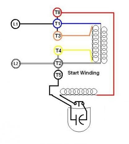
Terminal Identification
Two of the four terminals are red and the other two are green. How to distinguish between commencing winding terminals and running winding terminals is now the question. It is quite simple to recognize. The running winding often experiences less resistance than the initial winding.
So, get a multimeter and check the resistance between the two terminal pairs. The starting winding is winding with higher resistance, while the running winding is winding with less resistance. The starting winding terminals are shown in red in the above diagram, while the running winding terminals are shown in green.
Wiring Procedure
- By measuring the resistance, first identify the starting winding and running winding terminals.
- Any termination of each winding can be linked to the neutral terminal of the power supply by joining one of its terminals.
- Connect the running winding’s rest terminal directly to the power supply’s phase terminal.
- Connect a series-connected capacitor from the rest terminal of the beginning winding to the phase terminal of the power supply.
How to Wire a 3-Phase Motor?
In applications needing more than 7.5 horsepower, three-phase motors are frequently used since they are more efficient than single-phase motors. Black, red, and blue wires are frequently used to denote lines L1, L2, and L3, respectively, even though the National Electric Code does not specifically mention any specific conductor colors for three-phase current.
Each line’s voltage cycle is 120 degrees behind its predecessor’s, with L2 reaching its peak voltage after L1 and L3 after L2. The two wiring layouts, Wye and Delta, show how three-phase motors are wired. The most typical kind of dual voltage, the three-phase motor is covered by these instructions.
Step 1
Cut off the electricity to the circuit that will be connected to the motor. It is necessary to connect a three-phase supply to a three-phase motor.
Step 2
Locate the wires within the motor wiring box by opening it. Labels on the nine wires should read 1 through 9. In cases when a motor lead’s color can be used to identify it, refer to the motor documentation.
Step 3
Check the motor nameplate for wiring details. The motor voltages will be listed on the nameplate, which may also provide particular wiring details. Numerous motors may be connected for high and low voltages as well as for either Wye or Delta (sometimes called Y or Star wiring). Make sure the motor is wired for the correct voltage before connecting it.
Step 4
Use wire nuts that are the appropriate size for the number of conductors being joined together and the conductors being used to make all wiring connections.
If there is a neutral wire present in the conduit or cable powering the motor, it should be covered with a wire nut as it is not utilized for the motor’s three-phase wiring. Use a red wire nut, for instance, to join two 12-gauge wires together. Twist on a wire nut while holding the conductors’ bare ends together.
Step 5
To reverse the direction of the motor, switch any two-line connections. For instance, the motor will reverse direction if supply lines T1 and T2 are moved from T1 to T2, respectively. To make this modification, you can purchase motor control switches.
Frequently Asked Questions
What are P1 and P2 wires on a motor?
The whole induced power for the pump system is P1. P2 is the motor’s power output (shaft effect). The motor’s nominal power is P2.
Conclusion
There are starting winding and running winding on an Emerson electric motor. The motor is started using the starting winding and is kept running with the aid of the running winding. Black is typically connected with the neutral wire. White and black are connected to the two terminals of the particular capacitor in the same way.
Subscribe to our newsletter
& plug into
the world of circuits