Why Does My Neutral Wire Have Voltage – Fact Behind That
The voltage on the neutral wire is being conducted via that other load from the hot wire. Though the neutral wire is said to have zero volts, if you touch that wire on a live system, you will quickly discover that having zero voltage is not the same as having no electricity present.
Because they are all connected through the system ground, all neutral wires in the same grounded electrical system should have the same electrical potential. With a few notable exceptions, neutral wires are typically insulated for the same voltage as line conductors.
Common Reasons – Why Does My Neutral Wire Have Voltage
When you measure the voltage on the neutral wire in your electrical system, it can be an indication of several potential issues. Some of the common reasons why the neutral wire might have voltage include:
1. Imbalanced Load
In a perfectly balanced electrical circuit, the current on the hot/live wire should be equal to the current on the neutral wire, resulting in zero voltage on the neutral. However, if there is an imbalance in the load between the two hot/live wires (in the case of a split-phase or three-phase system), it can cause voltage on the neutral.
Solution: Ensure balanced loads on the circuits. Redistribute devices or appliances to equalize the current on the hot/live wires.
2. Loose or Damaged Connections
Poor electrical connections, such as loose or corroded wire connections at outlets, switches, or junction boxes, can lead to voltage on the neutral wire. These loose connections can introduce resistance and disrupt the balance between the hot/live and neutral wires.
Solution: Inspect and tighten all electrical connections. Replace or repair any damaged wires or components.
3. Faulty Neutral Wire
A compromised or damaged neutral wire can cause voltage irregularities. This could be due to a break in the neutral wire, a loose or corroded neutral connection, or a problem in the electrical panel.
Solution: Locate and repair any breaks or damage in the neutral wire. Ensure secure and clean connections in the electrical panel.
4. Grounding Issues
Grounding problems in the electrical system can affect the neutral wire. If the neutral and ground are not bonded correctly, or if there are grounding issues within the electrical distribution system, it can result in voltage on the neutral wire.
Solution: Check and correct grounding issues within the electrical system, ensuring proper bonding between neutral and ground.
5. External Factors
The voltage on the neutral wire can also be influenced by external factors, such as interference from other electrical circuits, power quality issues from the utility, or nearby equipment generating harmonics.
Solution: Address external factors if possible. Install harmonic filters if harmonic distortion is an issue.
6. Shared Neutrals
In some wiring configurations, multiple circuits may share a common neutral. If these circuits are not properly balanced or phased, it can lead to voltage on the neutral wire.
Solution: Reconfigure shared neutrals to ensure proper balance and phase alignment. Consult an electrician if needed.
Amount of Voltage on My Neutral
A common measurement of neutral-to-ground voltage in most office situations is around 1.5V. If the reading is high (more than 2V to 3V), the branch circuit may be overloaded. Another possibility is that the panel’s neutral is overloaded.
Current in Neutral Wire
In most nations, power is delivered to houses as a single-phase supply direct from the local area transformer. Each home is wired to a single-phase line, and the return current is sent back to the transformer through the neutral line. As a result, whatever current travels through the supply line also flows through the neutral.
Neutral Wire and Ground
Never connect the neutral and ground wires. This is incorrect and potentially hazardous. When you connect something to an outlet, the neutral becomes live because it completes the circuit. However, if something goes wrong and the neutral is disconnected, the device becomes unsafe.
Voltage Between Hot and Ground
120 volts is measured between the source hot and ground, and 120 volts between the hot lead and ground when the switch is turned on. Again 19 volts are received from neutral to ground in the lightbox when the light is turned off. There are 90 volts from hot to neutral with or without the bulb.
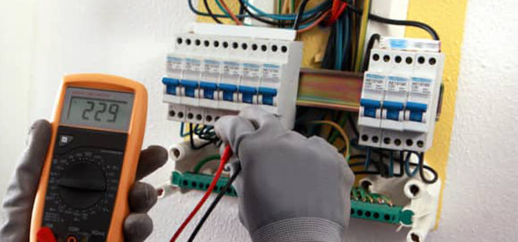
How to Test a Neutral Wire
Testing a neutral wire is essential to ensure that it is properly functioning in an electrical circuit. The neutral wire is a crucial component of the electrical system and is responsible for returning current safely to the source. Here are the steps to test a neutral wire:
Tools and Equipment
1. A digital multimeter
2. A non-contact voltage tester (optional)
Safety Precautions
Ensure that you have turned off power to the circuit you are testing. If you are working on a live circuit, exercise extreme caution and follow all electrical safety guidelines.
1. Testing with a Digital Multimeter
2. Testing with a Non-Contact Voltage Tester
Interpreting the Results: If the multimeter or non-contact voltage tester indicates voltage on the neutral wire when the circuit is powered on, there may be an issue with the neutral connection or a fault in the circuit. In this case, it’s essential to consult a qualified electrician to diagnose and address the problem.
Neutral Light Bulb
Normally, with the neutral route intact, 120 volts would be measured across the light bulb or receptacle. Because both sides of the light (hot and neutral) are the same in this scenario, there is no potential difference (voltage), and the bulb does not light up.
Frequently Asked Questions and Answers
What happens if neutral is open?
There is a disconnection in the white wire when you have an open neutral at a specific device. Electricity can still be sent to the gadget through the hot wire, but it cannot be returned to the panel. The device may not operate then, but you will receive a jolt from it since it is electrified.
Is it normal to have voltage on a neutral wire?
No, it is not normal to have voltage on a neutral wire in a properly functioning electrical circuit. The neutral wire should ideally have very low voltage, close to zero when compared to ground or earth.
Can a bad neutral cause high voltage?
Yes, a bad or compromised neutral connection can potentially result in high voltage on the neutral wire. When the neutral connection is poor or disrupted, it can lead to voltage imbalances in the circuit, causing higher voltages on the neutral wire and potentially creating unsafe conditions in the electrical system. A compromised neutral can also result in voltage fluctuations and issues with connected devices. It is essential to address any problems with the neutral wire to maintain the safety and proper operation of the electrical system.
Conclusion
It is also essential to remember that in many countries, the main plug we use may be flipped 180 degrees, placing the line where the neutral was intended to be. This means that with these types of systems, you can never be sure if your neutral is indeed neutral or line.
Subscribe to our newsletter
& plug into
the world of circuits

![[Explained] What Size Neutral for 200 Amp Service?](https://www.circuitsgallery.com/wp-content/uploads/2023/11/What-Size-Neutral-for-200-Amp-Service.webp)

I’ve gain a little hint about course,anyway help me to understand does it fair to tie neutral with earth from the outlets/plugs
When outlets are grounded, they’re connected to the Earth or a grounding system, which provides a path for excess electrical energy to safely dissipate in case of a fault or surge. This helps protect against electric shock and reduces the risk of electrical fires.
So, to answer your question, yes, it is definitely fair and crucial to tie neutral with the Earth in electrical outlets/plugs for safety reasons. This connection helps ensure that any potential electrical faults are safely redirected away from the user and the device. If you’re setting up or troubleshooting electrical systems, make sure to follow proper grounding practices to maintain safety and reliability.