What Happens if You Connect Neutral to Ground | Do Current FLow through the Neutral Conductor?
When the supply is normal AC, nothing happens in the case of industrial applications as they use a three-phase supply. When the phases are all loaded equally, no current flows through the neutral conductor.
However, in domestic applications, the ground wire becomes hot and it carries the majority of current as it has the least resistance. As a result, when a person comes in contact with a defective device, he/she will be exposed to an electric shock.
What will Happen If You Link Neutral with Ground?
Connecting neutral to the ground in an electrical system is a hazardous and incorrect practice that can lead to several issues and potential dangers:
1. Electrical Shock: When neutral and ground are connected, the ground wire becomes “hot,” carrying an electrical current. This can lead to electrical shock hazards. If someone touches a grounded object, like a metal appliance or a plumbing fixture, they could receive an electric shock.
2. Ground Becomes Unsafe: Grounding systems are designed to maintain a consistent voltage level with the Earth’s potential. When neutral is connected to the ground, the ground loses its safety function and becomes unsafe, potentially causing electrical hazards.
3. Inadequate Protection: The connection of neutral to ground can render protective devices, such as Ground Fault Circuit Interrupters (GFCIs) and Residual Current Devices (RCDs), ineffective. These devices rely on a balanced load between the hot and neutral wires. If neutral and ground are connected, the balance is disrupted, making them unable to detect ground faults and protect against electrical shocks.
4. Interference with Equipment: Connecting neutral to the ground can cause interference in electronic equipment and appliances, affecting their proper functioning. It can lead to equipment malfunctions or damage.
5. Violating Electrical Codes: This practice is a violation of electrical codes and regulations. Electrical systems must adhere to specific standards to ensure safety and functionality. Connecting neutral to the ground is a code violation and can lead to legal and regulatory issues.
6. Fire Hazards: If neutral and ground are connected, it can create potential overcurrent situations and lead to overheating in electrical wiring, which in turn can be a fire hazard.
How Can I Avoid Neutral-to-Ground Connections?
Connecting the neutral wire to the ground wire in an electrical circuit is a highly unsafe and incorrect practice that can have severe consequences. Here are specific points to understand why it should be avoided:
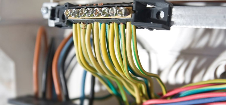
1. Color Coding of Wires
Electrical wires are color-coded for easy identification. The live or “hot” wire is typically black, red, yellow, or blue. The ground wire is usually green, while the neutral wire is white. Each wire serves a specific purpose in the electrical circuit.
| Wire Function | Color Recommended by NEC |
| Hot (Live) | Black, Red, or Any Color Except Gray, White, or Green |
| Neutral | White or Gray |
| Ground (Equipment Grounding Conductor) | Green or Bare (Uninsulated) |
| Ground (Isolated Grounding Conductor) | Orange with a Green Stripe |
| Ground (Water Bonding) | Green with Yellow Stripes |
| Conductor for Switching Devices (e.g., travelers) | Red or Blue |
2. Function of Hot, Neutral, and Ground Wires
3. Consequences of Connecting Ground to Neutral
4. Impact on Metal Cases
When neutral or live wire is mistakenly connected to the ground, any metal case connected to the ground will also become hot. Touching such a case could lead to electrical shock or other hazards.
5. Normal Circumstances vs. Emergencies
6. Role of Ground Fault Circuit Interrupter (GFCI)
7. Safety Precautions
The safe and correct practice is to never connect the ground wire to the neutral or vice versa. Proper wiring and adherence to electrical codes and regulations are essential to ensure the safety and integrity of the electrical system.
Answers to Your Common Questions
Why does a neutral wire have zero voltage?
The neutral wire has a voltage close to zero because it serves as a return path for electrical current in an alternating current (AC) circuit. Its voltage is relative to the hot wire’s voltage, resulting in a near-zero potential difference.
Does neutral carry voltage?
The neutral wire does carry voltage, but it typically carries a voltage close to zero volts concerning the ground or earth. It provides a path for current to return to the electrical source.
What happens if you don’t bond neutral to the ground?
Failing to bond neutral to ground properly can result in electrical safety hazards, including the risk of electric shock, as metal casings and surfaces may become energized. It also hinders the safe dissipation of fault currents and can affect the operation of protective devices like Ground Fault Circuit Interrupters (GFCIs).
Does neutral wire carry current?
Yes, the neutral wire can carry current in normal electrical circuits. It serves as a return path for the current supplied by the hot wire, completing the circuit.
What happens when you touch neutral to ground?
When you touch a neutral wire to ground, you typically shouldn’t experience an electric shock because the voltage difference between them is minimal. However, touching a neutral to ground could be dangerous if there are wiring faults or if they become bonded incorrectly.
Is it OK to connect neutral to ground?
It is not advisable to intentionally connect neutral to ground in a typical electrical system. Proper bonding of neutral to ground is essential to ensure safety and to facilitate the return of fault currents. In specific situations, such as in a subpanel, neutral and ground should be kept separate to avoid potential hazards and ensure system integrity.
Conclusion
In summary, it is essential to emphasize that connecting the ground and the neutral wires should be strictly avoided in any circumstance, particularly within a domestic setting. This practice is extremely hazardous and poses a significant risk of electrocution. Therefore, it is imperative to ensure that the neutral and ground are not connected in any manner to prevent such dangers.
Subscribe to our newsletter
& plug into
the world of circuits