DTMF Decoder Circuit Using M8870 | Schematic and Working Principle
A Dual Tone Multi-Frequency or DTMF decoder circuit identifies the dial tone from the telephone line and decodes the key pressed on the remote telephone. Here, for the detection of DTMF signaling, we are using the IC MT8870DE.
MT8870 is a touch-tone decoder IC. It decodes the input DTMF into 5 digital outputs. The M-8870 DTMF (Dual Tone Multi-Frequency) decoder IC uses a digital counting technique to determine the frequencies of the limited tones. And it also verifies whether they correspond to standard DTMF frequencies.
The DTMF tone is a form of one-way communication between the dialer and the telephone exchange. The whole communication consists of the touch-tone initiator and the tone decoder or detector.
Circuit Diagram of DTMF Decoder Circuit Using M8870
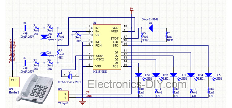
Credit: https://electronics-diy.com
Components Required for DTMF Decoder Circuit Using M8870
- DTMF decoder IC (M-8870)
- Resistors (100kΩ; 70kΩ; 390kΩ)
- Capacitors (0.1µFx 2)
- Crystal oscillator (3.579545MHz)
What is the Need of DTMF Decoding
In the premature days, human operators operated our telephone systems were in a telephone exchange room. The caller will pick up the phone, giving instructions to the operator to connect their line to the destination. It is a kind of manual switching. As more and more people entered into telephone technology as useful communication gear, manual switching becomes a time-consuming tedious task.
As technology was established, pulse or dial tone techniques were invented for telephone communication switching. It employs electronics and computers to support switching operations. DTMF is the ultimate technique used in any of the Mobile, Telephone communication systems.
The operation of DTMF method are as follows:
- Caller generates a dial tone consisting of two frequencies. It is transmitted via the telephone line (communication media).
- Telephone exchange consists of a DTMF decoder, which decodes the frequencies in to digital code.
- These codes are the address of destination subscriber; it is read and processed by a computer which connects caller to the destination subscriber.
Working of DTMF Decoder Circuit Using M8870
- DTMF keypads are employed in almost all landline and mobile handsets. Thus this technology is used in the telephone switching centers to identify the number dialed by the caller.
- The decoder distinguishes the DTMF tones and produces the binary sequence equivalent to key pressed in a DTMF (Dual Tone Multi Frequency) keypad.
- The circuit uses M-8870 DTMF decoder IC which decodes tone generated by the keypad of cell phone.
- DTMF signals can be tapped directly from the microphone pin of cell phone device. Cut the microphone wire and you will get two wires red and green. The red wire is the DTMF input to the circuit.
- The signals from the microphone wire are processed by the DTMF decoder IC which generates an equivalent binary sequence as a parallel output like Q1, Q2, Q3, and Q4.
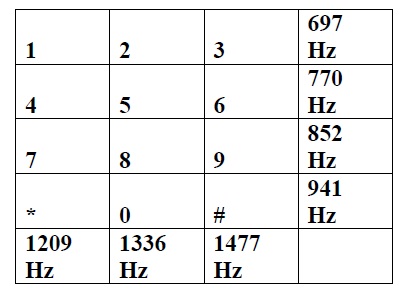
Table showing DTMF Low and High frequency tones and decoded output
- There is an inbuilt Op amp present inside the M-8870 decoder IC. The electrical signals from microphone pin are fed to inverting input of the Op Amp via a series of resistance (100kΩ) and capacitance (0.1 µF).
- The non inverting input of Op-amp is connected to a reference voltage (pin4 -VREF). The voltage at VREF pin is Vcc/2.
- Pin 3 (GS) is the output of internal Op Amp, the feedback signal is given by connecting the output pin (pin3- GS) to inverting input pin (pin2- IN-) through a resistor (270kΩ).
- The output of Op Amp is passed through a pre filter, low group and high group filters (filter networks). These filters contain switched capacitors to divide DTMF tones into low and high group signals (High group filters bypass the high frequencies whereas low group filter pass low frequencies).
- Next processing sections inside the IC are frequency detector and code detector circuits. Filtered frequency passed through these detectors.
- At last the four digit binary code is latched at the output of M-8870 DTMF decoder IC.
Uses of other pins
- The entire process from frequency detection to latching of the data, is controlled by steering control circuit consisting of St/GT, Est pins, resistor (390kΩ) and a capacitor (0.1µF).
- 5th Pin, INH is an active high pin, inhibits detection of A, B, C, D tones of character.
- 6th Pin, PWDN is an (active high), inhibits the working of oscillator thus stops the working of our circuit.
- The 10th pin 10; TOE is the output enable pin which is active high logic and enables the latching of the data on the data pins Q0, Q1, Q2, and Q3.
- 15th Pin StD is the Data valid pin, turn out to be high on detection of valid DTMF tone or else it remains low.
- Pins 7 (OS1) and 8 (OS2) are used to connect crystal oscillator. An oscillator of frequency 3.579545 MHz is used here.
Conclusion
Interestingly, from a DTMF decoder circuit using m8870, the decoded bits can be interfaced with a computer or microcontroller for further application. For instance –
- Remote control of home/office electrical appliances using a telephone network
- Cell Phone controlled home appliances
- Mobile phone-controlled robots
- And more …
Subscribe to our newsletter
& plug into
the world of circuits