Assemble A DIY Multimeter | Digital Voltmeter and Ammeter
We are all aware of multimeters such as voltmeters (voltage meters) and Ammeters (Ampere meters).
A voltmeter is nothing but a device used to measure voltage between given two terminals. Apart from basic usage, digital voltmeters are also employed as panel meters for automation systems and robotics.
On the other hand, an ammeter is an instrument used for electric current measurement in a circuit. The electric current passing through an ammeter is measured in Amperes (A).
You can find both analog and digital ammeters and voltmeters in the market. But you can easily build your own voltmeter and ammeter at a very low cost using some simple and common ICs and microcontrollers.
In this article, we are going to show how you can make your own PIC microcontroller-based digital voltmeter and ammeter with seven-segment display output with which you can measure voltage and current accurately.
So, what are you waiting for? Let’s make one by following the instructions below.
1. How to Build a Digital Voltmeter of Your Own
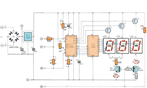
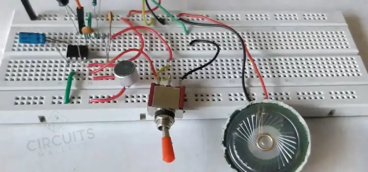
Here we have demonstrated how to build a digital voltmeter for DC voltage measurements without using multimeter testing. This is a simple digital voltmeter circuit that can measure voltages from 0V to 9V.
The main part of this circuit is a dotted bar display driver IC LM3914. Input voltage applied to this IC generates an output that is converted into a binary value. That is done by the priority encoder IC 74147.
You’ll need a common anode seven-segment display driver IC 7447 for the display of this voltmeter. However, the accuracy of this digital voltmeter schematic is limited to a sensitivity of 1V.
Circuit Diagram of Digital Voltmeter
Components Required for Electronics DIYers
- IC LM3914
- 74147 IC
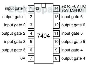
- IC 7404
- 7447 IC
- 7810
- Resistors(1.2k,3.3k,220)
- Common anode Seven segment display
How Does A Digital Voltmeter Work
- IC LM 3914 is a bar dot display driver which has 10 output pins (1 to 10). This IC has 10 comparators with a reference voltage each (1/10 to 10/10 of reference voltage)
- Each comparator output is low if the voltage to be measured is greater than the corresponding comparator’s reference voltage.
- The output of this IC is connected to a priority encoder IC 74147 which converts it into the corresponding binary value.
- Since the binary output is inverted, this voltmeter uses an inverter IC 7404 before giving it to the seven-segment display driver IC 7447.
- Here all IC’s supply is +5V, so for that, you can use 7805 connected in a similar way as 7810 in the circuit diagram.
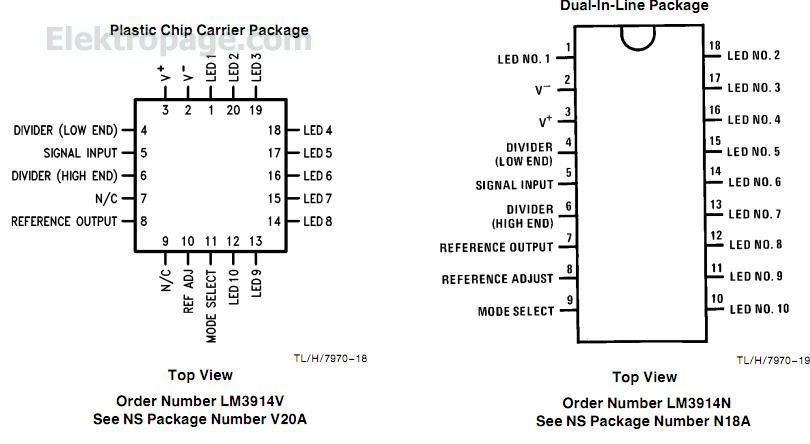
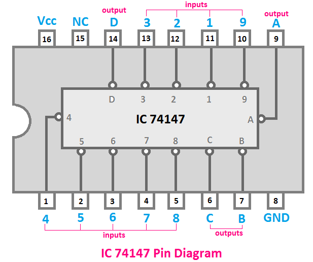
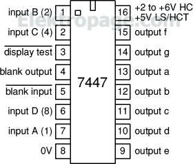
Components Pin Out
All the detailed process of making a digital voltmeter is described above. You just need to get familiar with a bunch of ICs that are involved with this voltmeter, and you can make your own custom one.
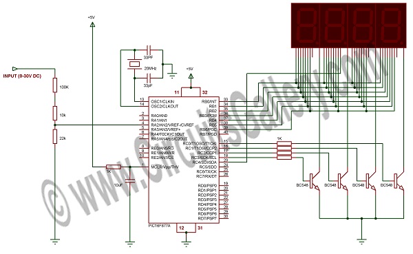
2. Digital Voltmeter Using PIC Microcontroller 16F877A and Seven Segments Display (0-30V)
Here we’re explaining the constructional details of the digital panel voltmeter using the PIC16F877A microcontroller. It can measure voltage between 0V to 30V DC. The seven-segment units are provided for the digital voltmeter display which gives clear visibility of digits from a long distance compared to the LCD display.
The program for the digital voltmeter is compiled using Micro C. Now, let’s see how we can build it.
Circuit Schematics of Digital Voltmeter Using Pic Microcontroller
The following figure shows a digital voltmeter panel circuit diagram with Microchip PIC.
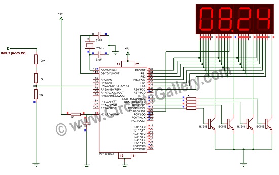
Components Required for Digital Voltmeter Using Pic Microcontroller
- PIC16F877A Microcontroller
- Transistor (BC548 x4)
- Resistor (1KΩ x 5; 10KΩ; 100KΩ; 22KΩ)
- Seven-segment Display x8
- Crystal (20MHz)
- Capacitor (10µF, 33PF x2)
Working on Digital Voltmeter Using Pic Microcontroller
- PIC programming is quite easy if you have a perfect C compiler like Micro C pro, MPLAB Hi-tech C, etc.
- PIC16F877A has an inbuilt ADC (Analog to Digital Converter) Module, I used ADC to read input voltage values.
Measuring Voltage and Design of Voltage Divider Circuit
- First of all, let me discuss how we can measure voltage. Actually, PIC’s ADC can measure 0V to +5V, but here our voltage range is 0V to +30V.
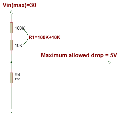
- Hence, we can’t feed the input voltage directly to the controller’s ADC pins. Instead of feeding directly, the input voltage is reduced by a combination of voltage divider resistors.
The maximum allowed drop will be 5V.
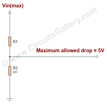
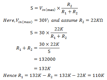
We got R1=110KΩ, but a 110KΩ standard value resistor is not available, so use a series combination of 100KΩ and 10KΩ.
Note: – If you want to increase the input range, let’s say 0V to 100V change the above equations accordingly.
Calculating Actual (Real) Input Voltage From Voltage Divider Circuit
- As per our circuit diagram PIC microcontroller reads the voltage across a 22KΩ resistor. To calculate the voltage across the 22KΩ resistor by the voltage divider rule.

Mapping ADC Values to Input Voltage
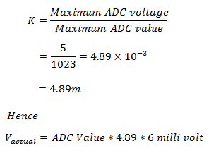
- PIC microcontroller ADC is a 10-bit ADC, which means the output of ADC can vary from 0 to 1023 maximum while input varies from 0 to 5V.
- That is when the input voltage is +5V then the ADC value is 1023 when the input voltage is 0V ADC value will be 0.
- We have to map 0 → 1023 to 0 → 5; it can be done by multiplying the ADC value with a constant K.
- This will be a 5-digit mili volt value, to get the real value put period (.) after 1st two digits. We have 4 seven segment display units, to remove the last digit just divide by 10.
For example, let’s say the ADC value is 1023
Vactual=1023*4.89*6 Milli volt=30014 millivolt
This number is displayed on the LCD screen after dividing by 10 which is 3001. We are enabling the DP (dot) pin of the 2nd unit to get real voltage.
Converting Number to Seven Segment Data
- I separated this value into four digits by modular division i.e., 3001 is converted to 3, 0, 0, 1.
- That is 4th Digit = value%10, 3rd Digit = (value/10)%10, 2nd Digit = (value/100)%10, 1st Digit = (value/1000)%10.
3001%10=1;
(3001/10)%10=0;
3001/100)%10=0;
3001/100)%10=3
Hence, 3001 is separated into 3, 0, 0, 1, and it is displayed by 30.01 on seven segment units.
- These individual values are converted to corresponding seven-segment data and displayed by the technique Seven segment multiplexing.
Local digital voltmeters can only check voltages. But if you want to use it for more complex projects like robotics, then you can easily modify the voltmeter or make it more user-friendly using a PIC microcontroller and seven-segment display.
3. Digital Ammeter Using PIC Microcontroller 16F877A and Seven Segments Display (0 to 10A)
We’re going to show you the building process of a Digital Ampere meter that measures the current from 1 to 10 Ampere. To make this Digital Ampere meter, you’ll need a PIC Microcontroller 16F877A and Seven Segments Display (0 to 10 A). You can use it to measure the current flowing through a load/circuit easily and the seven-segment display shows it digitally.
Let’s learn the detailed process of how to make a digital ammeter below.
Circuit Schematics of Digital Ammeter Using Pic Microcontroller
Where the load is an LED, you can connect any load.
Components Required
- PIC16F877A
- Transistor (BC548 x8)
- Resistor (1K x8, 10K, 100K x2, 22K, 330 x2, 0.47/2W)
- Seven-segment Display x8
- Crystal (20MHz)
- Capacitor (10uF, 33PF x2)
Working
- PIC has an internal ADC (Analog to Digital Converter) Module, which we have used here to read the analog current value.
- In our digital voltmeter article, we have seen the calculation of voltage via potential divider networks. Now let’s see the mathematical calculation of the current. The current calculation may be a little bit confusing as compared to voltage.
- ADC module of PIC can measure 0 to +5V since the Vcc is +5V DC.
Calculating Current Through the Load
- Input current is not directly fed to the microcontroller used in this Digital Ammeter circuit project, it’s reduced by a 0.47Ω resistor; the voltage drop across the 0.47Ω resistor is read by the ADC.
- Then the ADC value is multiplied by a constant called the ADC constant for obtaining the real value of the current.
Mapping Adc Value to Input Current
- The output of a 10-bit PIC Microcontroller ADC may vary from 0 to 1023 while input varies from 0 to +5V.
- Hence, we have to map 0 → 1023 to 0 → 5 which can be done by multiplying the ADC value with a constant K.
In our case to get the real Vadc, multiply ADC input to a constant K (0.00489). - This constant can be obtained from an equation,
For example, consider ADC value is 1023 (Vadc=5V& v = 10233)
Multiply this 10.63 by 100 to get 1063. These values can be separated and displayed on seven segment screen.
Separating Values
Well, we have 1063, and the real value is 10.63, so enable the dot (.) segment in the second display unit.
Then do modular division,
1063%10 = 3
(1063/10)%10 = 6
(1063/100)%10 = 0
(1063/1000)%10 = 1
Hence, we separated all the digits. Now send those digits to seven segment display by the technique of seven-segment multiplexing.
Having an ammeter is a must for any electronic enthusiast. If you don’t have one, you can easily make your own using some simple components like a PIC microcontroller and following the instructions given above.
Conclusion
Why should you buy a voltmeter when you can make one of yours? Here we have demonstrated the step-by-step process of making digital multimeters including voltmeters and an ammeter. If you’ve read this article thoroughly, you’ll surely be able to build a custom digital multimeter according to your preferences. So, hopefully, this guide has proven helpful to you and if you’re still having any confusion regarding this topic, feel free to share in our comment section below.
Subscribe to our newsletter
& plug into
the world of circuits