Duplex Intercom Circuits | Schematic and Working Principle
An intercom system provides two-way communication free of cost. It can be advantageous in hospitals, hotels, and businesses to make communication simple and completely free. You can also use this to communicate with your nearby friend.
If you are searching for a completely free communication method in your home, school, university, office, hospital, or other similar small regions, then the intercom is the best option for you. It can be more cost-effective if you make your own intercom using simple ICs and mics.
Luckily, we have provided the schematic, diagram, and working principle of a simple two-way intercom circuit in this article, and you can also learn about the duplex intercom circuit schematic (a two-way door phone intercom circuit) in the second segment of this article.
So, without any further ado, let’s move to the point below.
Simple Two Way Intercom Circuit Diagram and Schematic
You may already know that an intercom or Intercommunication circuit is a two-directional communication system that provides a reliable communication line and is extremely easy to implement. You can easily make this circuit using an amplifier, two switches, and two loudspeakers.
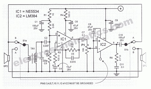
Furthermore, you can also extend this circuit by adding more speakers with the help of switches. The IC LM384 works as a power output amplifier in this intercom circuit and the LM384 provides almost 2 watts of audio power via 15 volts supply voltage.
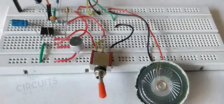
The working process of this intercom circuit diagram is very simple and practical. Now, let’s see how you can make it in the most simple way.
Simple Two Way Intercom Circuit Diagram
Components Required for an Intercom System
- Power supply (15V)
- Resistors (1kΩ x 2; 5.6kΩ; 22kΩ; 100Ω x 2)
- Preset (10kΩ)
- Capacitors (0.01µF; 0.1µF x 2; 0.047µF, 220pF)
- Electrolytic Capacitors (10µF:25V; 100µF:25V x 3; 47µF:25V x 2)
- Transformer (220/6V step-down)
- NE5534
- LM384
- Speaker/ Microphone (8Ω)
- 2 Way Switch x 2
Working of Wired Intercom
- Here the 8Ω speaker acts as a Microphone as well as Speaker according to the switch positions.
- If switch S1 is in ‘Talk’ contact, L1 functions as a Microphone.
- If it is in the ‘Listen’ position, L1 functions as a Speaker.
- Similar case is applicable in S2 and L2 too
S1 in Talk Position
- Time being let’s consider S1 is in the ‘Talk’ position and S2 in the ‘Listen’ position.
- Since most speakers are available with low impedance, an impedance converter is required to retain high-quality audio.
- Impedance matching is done by the transformer T1. (This transformer is an ordinary 220/6V step-down transformer.)
- IC NE5534 works as a Pre Amplifier which boosts the Audio signal before applying it to the LM384 amplifier section. The gain of the LM384 op amp amplifier is set to 11.
- The output volume can be adjusted by varying the R4 preset.
- In order to use this circuit as an intercom, the bandwidth is chosen to be 160 Hz to 10 kHz. Selection of other bandwidth range results in a HIFI amplifier.
- Place the power supply unit independently from the main circuit to avoid interference.
S1 in Listen Position
- By changing the switch positions of S2 into ‘Talk’ position and S1 to the ‘Listen’ position, L2 get connected to the input section, and L1 connected to the output section.
- Then L2 functions as a Microphone and L1 as Speaker.
Thus 2 directional communications are achieved! And the circuit can easily be used for house intercom or home intercom systems.
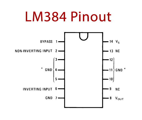
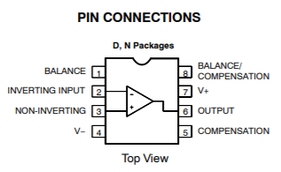
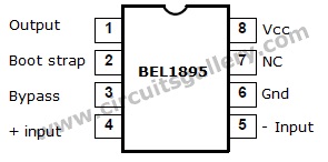
Required Components Pinouts
Intercoms are costless communication systems to contact within small regions such as homes, schools, universities, and offices. Hence, it’s always handy with design hacks for this simple two-way intercom circuit that you can see above.
Simple Door Phone Intercom Circuit Schematic (Duplex)
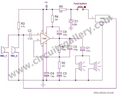
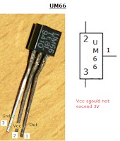
The door phone intercom system also provides a two-way conversation free of cost, and you can easily make this circuit using an 1895 IC, a 1-watt audio amplifier, two condenser mics, and two speakers for communication. To generate the calling tone, you can use the melody generator IC UM66. Let’s learn more about his circuit below.
Advantages of Duplex Intercom Circuits
There are other two-way communication intercom circuits having switching troubles and disadvantages. Namely, they use the same speaker both as the mic and speaker based on the switch positions. This door phone intercom circuit is devoid of such.
Here are some of the advantages of these intercom systems for the home:
- Low noise communication.
- It is a duplex intercom, so the two persons can talk simultaneously.
Door Phone Intercom Schematic
Components Required for Door Phone Intercom Circuit
- Condensor mic X 2
- Resistors(4.7K,330×2,100k,33k)
- Capacitors(.22uF,100uF,220uF,10uF,470pF,470uF)
- Zener diode 3.3V
- UM66 IC
- Push button
- Speaker
- IC 1895
Working Principle of Door Phone Intercom Circuit
- Two condenser mics are connected in parallel which is biased by a resistor R3.
- C2 and C1 are input and output coupling capacitors respectively. They are used to avoiding DC shifts.
For simplicity, let us divide the whole circuit into 3 parts-Input, Amplifier, and Output sections.
- The first section consists of mics and the tone generator. The output of tone generator IC UM66 has a connection in parallel with the condenser mic for amplification.
- Second is the amplifier section which consists of the amplifier IC 1895.
- The output section consists of two 8-ohm speakers connected in parallel which reduces the total impedance to 4 ohms. So there is an impedance matching between the speaker and amplifier IC. Hence, there is maximum power transfer (i.e. maximum efficiency).
Components Pin Out
Though this door phone intercom circuit system is for short-range applications, you can still extend it for long-range with the help of audio repeaters. Moreover, you can make it wireless by connecting FM transmitters and receivers.
Conclusion
The schematics and working diagrams of the two-way intercom circuit and the door phone intercom circuit are demonstrated in this article, and we hope, now you can make your own intercom to establish free communication in your place after reading this guide. If you have any confusion or other queries regarding this topic, don’t hesitate to ask in our comment section below.
Subscribe to our newsletter
& plug into
the world of circuits
