Basic DAC and ADC Circuits – How to Build
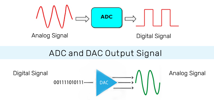
The Digital-to-Analog Converter (DAC) and the Analog-to-Digital Converter (ADC) circuits are discussed here.
A Digital to analog converter (DAC) converts binary digital data to an analog form by using an R-2R ladder (binary weighted resistor) network and a summing amplifier. It uses an op-amp (741) as a summing amplifier.
You can learn how to build aDigital to Analog converter using the simple technique explained in detail. Here is the circuit and output simulated waveform of Digital to Analog Converter Using the R-2R Ladder Network.
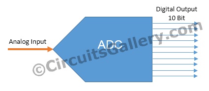
An ADC (Analog to Digital Converter) is an electronic circuit that converts its analog input to a corresponding binary value. To do this operation you’ll need Analog to Digital converter ICs.
You easily can make this 2-bit ADC using LM324 comparator IC, a potential divider network, and some combinational circuits.
You can find the ADC tutorial here ADC using LM324 IC.
While dealing with microcontrollers, you may face many situations where you have to use ADCs such as Digital voltmeters, ammeters, etc. and in such cases, it’s difficult to set up a separate ADC hardware circuit for our project.
Fortunately, the PIC microcontrollers have an inbuilt ADC module making it easy to Analog to Digital conversion. You will be able to program a PIC microcontroller for manipulating the ADC module after reading this ADC tutorial.

So, before going to the circuit diagram and embedded program, you need to figure out some details about ADC in PIC and also ADC and inbuilt library functions in Micro C.
Everything you need to know about these circuits are described in this article, and we hope you can learn much detailed information regarding these topics from below.
1. DAC | Digital to Analog Converter Using R-2R Ladder Network and 741 Op Amp With Simulated Output Waveform
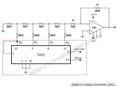
Let’s learn in detail about Digital to Analog Converter Using R-2R Ladder Network and 741 Op Amp With Simulated Output Waveform below. First, let’s check the Circuit Diagram of Digital to Analog Converter.
Circuit Diagram of Digital to Analog Converter Using R-2R DAC and 741 Op Amp
Components Required log Digital to Analog Converter Using Op Amp
- Resistors (1KΩx4, 2KΩx5)
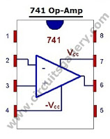
- 741 Op Amp
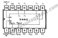
- 7493 Counter IC
Working Principle of R-2R ladder network DAC
- R-2R weighted resistor ladder network uses only 2 set of resistors: R and 2R. If you want to build a very precise DAC circuit, be precise while choosing the values of the resistors. They should exactly match the R/2R ratio.
- This is a 4 bit DAC network. Consider the digital data D3D2D1D0= 0001 is applied to the DAC.
- Then the Thevenin equivalent circuit reduction is shown below.
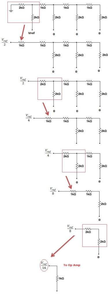
- Vref is nothing but is the input binary value reference voltage. That is for binary 1, Vref=5V. And for binary 0, Vref=0V.
- For 0001 only D0=Vref. All other inputs are at 0V i.e. they can be treated as ground.
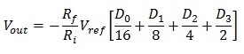
- So finally Vref/16 volt is appearing as the input to op amp. This value gets multiplied by the gain of op amp circuit “–(Rf/Ri)”.
- If we proceed in this manner (Thevenin equivalent reduction), we will get
- Note that you can build a DAC with any number of bits you want. For that, simply rnlarge the resistor network by adding more R-2R resistor branches.
- In this circuit the 7493 IC is simply provides digital inputs to the DAC. It is a counter IC and not an integral part of the DAC circuit. You can apply any combinations of binary inputs to D3D2D1D0
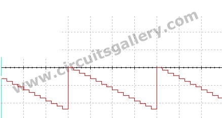
Output waveform of DAC circuit
Components pin out
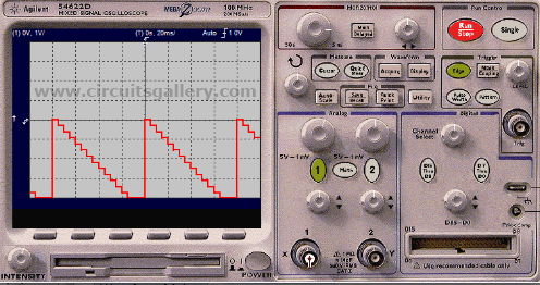
Practical signals, whether audio, video, or photo, are all analog in nature. But digital circuits and devices we use are yet to grasp and analyze them directly in analog. They convert the signals to digital for processing. Thus, in the output terminals, our required signals are to be retrieved. As a result, Digital to Analog Converter Using R-2R and ap-amp has this much significance.
2. What Is Analog to Digital Converter | ADC Using LM324 IC
As we described above that Analog to Digital converter converts analog signals into binary or digital signal. Now, let’s see how ADC works using LM324 IC from the section below.
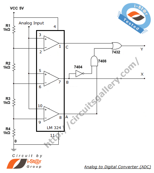
Circuit Diagram of Analog to Digital Converter Using LM324 IC
Components Required for the ADC Circuit
- Resistors (1Kx4)
- IC LM324
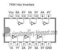
- 7404 IC
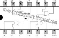
- IC 7432
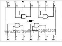
- 7409 IC
Design of Analog to Digital Converter
Truth tables and K-maps are quite essential before you deal with the digitalizing operation.
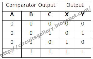
Truth Table of 2-bit ADC Converter
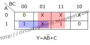
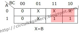
K-Maps for ADC
Working of the Analog to Digital Converter Circuit
- If the analog input exceeds the reference voltage to any comparator, that comparator turns ON.
- But, if all the comparators are OFF, the analog input signal will be between 0 V and +Vref/4.
- If Ci is high and others OFF, then the input must be between +Vref/4 and +Vref/2.
- And when C2 is high Ci is low, then the input must be between +Vref/2 and +3Vref/4.
- Again if all the comparators are ON, then the input must be between +3Vref/4 and +Vref.
- Simultaneous ADC is also called flash ADC and the speed of conversion is highest. However, the complexity of the useful circuit increases as the resolution is increased.
Components Pin out
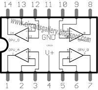
LM324 is such an efficient IC that it can operate within a range of 3 to 32 volts. Thus, in the context of analog to digital converter, it’s evident to use it. It contains a quadruple of op-amps that help set analog signals to digitalize effortlessly.
3. Analog to Digital Converter Using PIC16F877A Microcontroller | Beginners Guide
The detailed process of analog to digital conversation using PIC16F877A Microcontroller is explained below. So, let’s read the next section below and make a new ADC for yourself.
ADC Register in PIC Microcontroller
- ADC (Analog to Digital Converter) module is offered in many PIC MCU models.
- The Analog-to-Digital (A/D) Converter module has eight inputs for the 40 pin PIC Microcontrollers.
- In PIC16F877A, PORTA is multiplexed with ADC register, Comparator, and Digital I/O operations. Due to the availability of ADC, PORTA is also known as an Analog port.
- In order to work on ADC, we must configure the ADC register in a proper way.
- In PIC MCU, the conversion of an analog input signal effects in an equivalent 10-bit digital number (10 bit ADC).
Micro C ADC Library and Important Library Routines for ADC Module
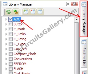
Micro C Library functions provide a comfortable platform for working with the ADC module in PIC. The only thing that we should add is the LCD library from the library manager.
What Is the Use of ADCON1 (Analog to Digital Control Register)?
The ADCON1 register configures the functions of the port pins. The port pins can be configured as analog inputs or as digital I/O according to the value in the ADCON1 register. In our program, we have used ADCON1=0x80 because we are using PORTA as an Analog input port.
adc = ADC_Read(1)
This will read the analog value from channel 1 (PORTA.F1) and save it to a variable ‘adc’ after converting it into a 10-bit digital value.
What Is the Use of Cmcon (Comparator Control Register)?
PIC has two analog comparators multiplexed with PORTA, and these comparators can be operated in 8 different modes with respect to the values in the CMCON register.
Here I’m showing only 1 mode that is disabled comparator mode, all other modes are out of our interest.
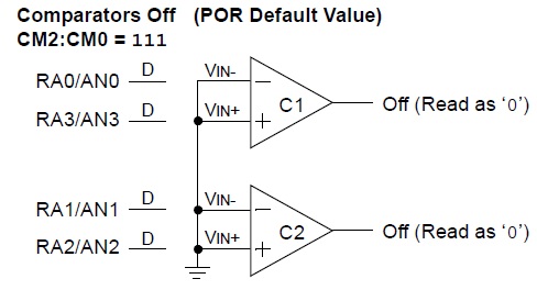
For ADC operation we don’t need the CMCON register. So we are turning OFF the comparator by setting CMCON=0x07 (0x07=0000 0111).Thus the status of CMCON should be-
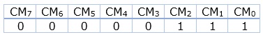
It will turn OFF the comparators.
If you got an idea of the above codes let’s start our Mikro C programming. The program is very simple and only the 3 codes are new to you.
Circuit Diagram of ADC Using PIC16F877A
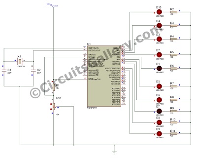
Components Required for Analog to Digital Converted
- PIC16F877A
- Crystal Oscillator (Select frequency according to you)
- Ceramic Capacitor (22pF x 2)
- LED x 10
- Resistors (100Ω x 10, 1/4 Watt)
PIC LCD Module Micro C Program
In this program, PORTB and 2 bits of PORTC (RC7, RC6) are used to display the output since ADC output is 10 Bit and the program works on the do–While loop.
unsigned int adc; // Variable to save ADC value
void main() // Start of Main function
{
    CMCON = 0x07; // Disable Comparators
    ADCON1 = 0x80; // For ADC Module configuration
    TRISA = 0xFF; // PORTA is input (ADC Input)
    TRISB = 0x00; // PORTB is output
    TRISC = 0x00; // PORTC is Output
    do
    {
        adc = ADC_Read(1); // Get 10-bit results of AD conversion of channel 1
        PORTB = adc; // Send lower 8 bits to PORTB
        PORTC = adc >> 2; // Send 2 most significant bits to RC7, RC6
    } while(1);
}
You have to burn the hex file generated after the whole process of building the analog to digital converter using PIC16F877A.
Conclusion
Everything about the analog to digital converter and digital to analog converter including how they work using LM324 comparator IC, R-2R Ladder Network, 741 Op Amp, and PIC16F877A Microcontroller are described above in this article. So, we hope, you’ve found this guide helpful and gathered all the basic knowledge about DAC and ADC circuits after reading this article. If you have any queries or confusion regarding this topic, don’t hesitate to ask in the comment section below. Thanks for reading.
Subscribe to our newsletter
& plug into
the world of circuits

![[Answered] What Size Wire for 125 Amp Service?](https://www.circuitsgallery.com/wp-content/uploads/2023/10/What-Size-Wire-for-125-Amp-Service-.webp)
