Interfacing Microcontroller with LED and LCD
Interfacing microcontroller with LED (Light Emitting Diode) and LCD (Liquid Crystal Display) is quite interesting and if you don’t know how to make LEDs or LCDs interface with PIC microcontrollers, and wish to study the basics of embedded microcontroller programming then this article is just for you.
LED interfacing is the stepping stone for microcontroller development. On the other hand, LCD is exclusively manufactured to be used with microcontrollers, which means that usual IC circuits cannot trigger it.
In this embedded program, we are going to show how you can connect the PIC to an LCD and an LED module with microcontroller programming. So, without any further ado, let’s start with the beginner’s guide about Interfacing Microcontrollers with LCD.
1. LCD Interface With PIC Microcontroller | Beginner’s Guide
Here we have discussed a 16×2 LCD interface with the PIC microcontroller that can display 2 lines with 16 characters each. Every character consists of a 5×8 or 5×11 dot matrix.
Moreover, it can display all the letters of the alphabet including the Greek alphabet, mathematical symbols, punctuation marks, etc. It is also likely to display symbols according to your preferences.
Other positive features are –
- Automatic message shift (left and right),
- Cursor appearance,
- LED backlight, etc.
Interfacing LCD to microcontrollers is quite simple to program for beginners and easy to understand. Let’s learn about it in more detail below.
Pin Description of LCD Display Module
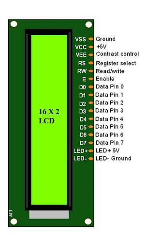
EN – Enable:
This control line is used to inform the LCD that you are sending in data. To send data to the LCD, input data on the data bus, then make EN high (1) and wait a little bit, and end by bringing EN to low (0) again.
RS – Register Select:
When RS is low (0), the information in the DB0 to DB7 pins is to be considered as an instruction (command- such as Clear screen, Display set, etc.). When RS is high (1), the information in the DB0 to DB7 pins is to be considered valid text data to print on the LCD screen. For example, to display the letter “i” on the screen you should set RS= high.
RW – Read/Write:
When RW is low (0), the information on the data bus is written to the LCD module.
DB0 to DB7:
Data bus lines of LCD display.
LED+, LED-:
Used for enabling backlight on the screen. If you don’t want the backlight you can leave it unconnected.
Basic Connection Circuit Diagram of LCD Interfacing With PIC
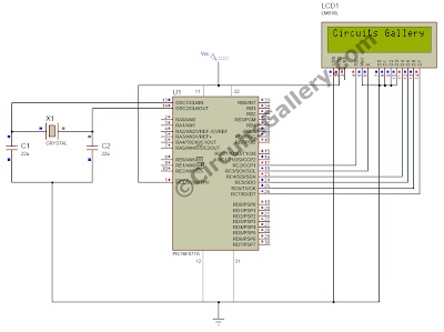
- We can interface LCD to PIC in 4-bit mode
- So D0, D1, D2, D3 of LCD display are grounded since the connection is 4-bit mode and the D4, D5, D6, D7 are connected to Port C higher bits RC4, RC5, RC6, RC7 respectively.
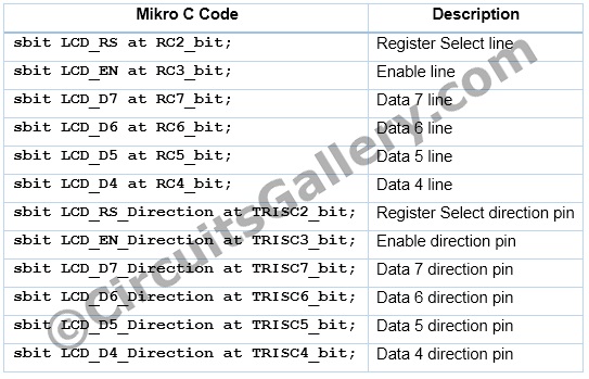
- RS pin of LCD module connected to RC2 (PORTC.F2), this will decide whether the LCD inputs are data input or instruction input. In the case of the Micro C compiler, we don’t bother about this pin, only we need to initialize it as sbit LCD_RS at RC2_bit; the rest of all the operations are done by the LCD Library function inside Micro C.
- RW (Read/Write) pin grounded because we are writing to LCD display. (For writing RW=0; For reading RW=1;)
- Enable (EN) pin connected to RC3 (PORTC.F3), a HIGH to LOW transition of this pin is needed in order to transfer data or command from PIC to LCD module. As I said above, the Micro C LCD library function will do the job for us. Just initialize the bit as sbit LCD_EN at RC3_bit;
Micro C LCD Library
The Micro C PRO for PIC offers a library for communication with LCDSs over the 4-bit interface. For executing LCD commands we should add this LCD Library file to the program code.
Go to Library Manager → then add Lcd_Constants and Lcd
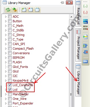
External Dependencies of LCD Library in Micro C
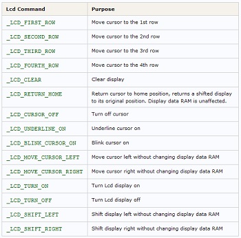
Below shows the table including all the initialization commands in the LCD library of Micro C.
Important Library Routines for LCD Module
Lcd_Init();
Initializes LCD module to work with PIC Microcontroller.
Lcd_Out(row, column, “Text”);
Writes text on LCD beginning from the definite position. Both string variables and literals can be passed as a text. row: starting position row number column: starting position column number text: text to be written
Lcd_Cmd(_LCD_CLEAR);
Sends command to LCD.
Different types of commands are used in the LCD library function, the available commands are shown below.
Algorithm for LCD to PIC Program
- Configure LCD module pin connections.
- Set PORTC as an Output port.
- Setup LCD display.
- Send data to LCD display.
LCD Interfacing Embedded C Program for PIC MCU
The enable pin of LCD i.e. the 6th pin needs a 1 to 0 transition with a small delay in order to process the input lines. That’s why we are providing a small delay in between all functions.
That’s all you need to know about LCD interfacing with PIC microcontrollers as a beginner. Now, let’s move on to the advanced level of this project.
2. LCD Interface With Microcontroller PIC
As you’ve learned about the interfacing of LCD with microcontroller PIC in the previous section of this article, now let’s move to the little-bit advanced level of interfacing. The following embedded program shows the interfacing of LCD with Microchips PIC 16F77A Microcontroller. Here 16×2 LCD is interfaced with the microcontroller.
Note: Data bus of LCD is connected to PORT B, 0th and 1st pins of PORT C are used as control pins.
Program of LCD Interfacing With Microcontroller PIC
#define RS PORTC.F0
#define EN PORTC.F1
#define DB PORTB
void lcd_cmd(unsigned char cmd)
{
RS=0;
DB=cmd;
EN=1;
delay_ms(10);
EN=0;
}
void lcd_dat(unsigned char dat)
{
RS=1;
DB=dat;
EN=1;
delay_ms(10);
EN=0;
}
void main()
{
TRISB=0x00;
TRISC=0x00;
lcd_cmd(0x38);
lcd_cmd(0x0C);
lcd_cmd(0x01);
lcdcmd(0x81);
lcd_dat('i');
lcd_dat('-');
lcd_dat('S');
lcd_dat('t');
lcd_dat('@');
lcd_dat('r');
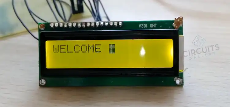
}Working Images and Outputs
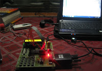
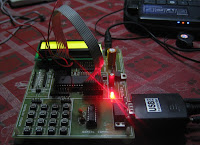
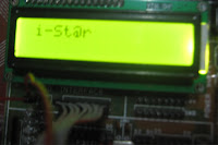
Here we have displayed the word ‘i-St@r’ on the LCD screen. Moreover, the above program is tested and verified under the i-St@r laboratory.
3. LED Interfacing With PIC Microcontroller | Embedded C Program With Circuit
This is a simple embedded program for PIC 16F877A to interface LEDs which is developed through the Micro C compiler, one of the best solutions for embedded programming in the PIC family.
It is compatible with Windows XP and Windows 7 platforms and comes with internal burning tools. Let’s learn more about this PIC circuit as a beginner and explore the world of microcontrollers below.
Algorithm for Implementing This Pic Project
- Specify the output port [here PORT B is used to connect LEDs, So TRISB=0x00; the comment is used for specifying the output port]
- Start infinite loop [while(1){} is used here]
- Pass 0x00 value to the output port [PORTB=0x00;]
- Provide a delay. The inbuilt delay function, that is delay_ms(); gives some delay. You can change the duration of LED blinking by giving any value to the calling field of this function. For example delay_ms(1000); will give 1 second delay.
- Pass 0xFF value to the output port [PORTB=0xFF;]
- Provide a delay [delay_ms(1000);]
- Repeat the loop.
LED Interfacing Embedded C Program for PIC Microcontroller
void main()
{
TRISB=0x00;
while(1)
{
PORTB=0x00;
delay_ms(1000);
PORTB=0xFF;
delay_ms(1000);
}
}
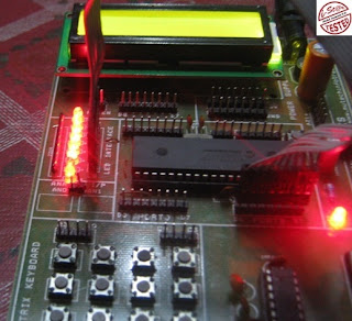
The while loop will execute infinitely. So all 8 LEDs connected to PORT B start blinking with 1-sec delay.
Circuit Diagram of PIC Project
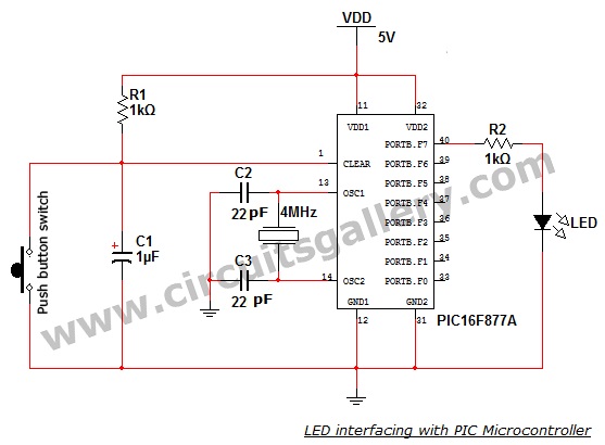
Just follow this circuit diagram above and start your own PIC microcontroller programming with LED.
Conclusion
LED interfacing is a very basic project to door to enter the world of PIC microcontrollers and also the LCD interface with a PIC microcontroller is often an important step in accomplishing a number of projects. Most mid-level to advance projects require a display to let know their status, and we have tried to cover almost all you need for your mid-level to advanced projects. We hope, this article will help you to start with PIC microcontroller programming and go further.
Subscribe to our newsletter
& plug into
the world of circuits

