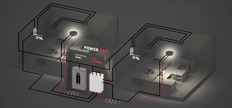
A lighting inverter usually has six wiring diagrams. They consist of typical diagram, standard switched lighting zone, dimming or switched lighting zone, 3 way dimming or switched lighting zone, two switched lighting zones in case of using the switched command signal and normally-off as a bypass, and two switched lighting zones using normally off bypass and switched output.

Lighting Inverter Wiring Diagram | 6 Wiring Diagrams
There are different cases for wiring a lighting inverter. The main advantage of the flying leads is enabling to use of a wall switch or some other on/off control device on the emergency fixtures. To do this, you need to insert the inverter between the switch and the emergency fixtures. Here are the wirings diagrams of a lighting inverter.
Typical Wiring Diagram

Standard Switched Lighting Zone Using the Switched Command Signal

Dimming or Switched Lighting Zone Using Normally off as a Bypass

3 Way Dimming or Switched Lighting Zone Using Normally off as a Bypass

Two Switched Lighting Zones Using the Switched Command Signal and Normally off as a Bypass

Two Switched Lighting Zones Using Normally off Bypass and Switched Output

How Do I Wire an Inverter Light?
To wire an inverter light, connect the line output of the wall switch to the black or orange flying lead instead of connecting the flying lead to the un-switched AC feed. Now the emergency fixtures can be switched on or off during normal power conditions and during a power loss, the inverter will ignore the position of the switch and operate the emergency load a full brightness.
Then connect the output of the inverter to the emergency fixtures. Connect the grey output wire to the shared neutral wire of the emergency fixtures. After that, connect the yellow violet wire to the 120 to 277 line volt wire. Never connect the grey output wire to the neutral input wire.
What Is a Lighting Inverter?
In the event of an emergency, a lighting inverter transforms DC battery power into typical AC voltages to power lighting systems. Many times referred to as a “UPS (Uninterruptible Electricity Supply) for emergency lights. Some inverters also offer continuous, filtered power for various lighting types.
Inverters for emergency lighting are made for a variety of uses, including those that are not strictly related to emergency lights. An emergency lighting inverter frequently supports fire alarm systems, emergency lighting, exit lighting, lighting control systems, and other vital or life safety-related equipment.
Conclusion
Lighting inverters are quite useful in emergency cases. The wiring of these inverters is not difficult. However, there are some cases you should be known of. Due to the difference in installment approaches, the wiring diagram can change accordingly.
Leave a Reply